
Add two more TX/RX Channels to your LXX Bit
Home › Forums › Bit Char-G, Digi-Q and other Micros › Bit CharG and Micro Radio Controlled – Technical › Add two more TX/RX Channels to your LXX Bit
- This topic has 29 replies, 9 voices, and was last updated 21 years, 11 months ago by
jevries.
-
AuthorPosts
-
-
February 7, 2004 at 8:59 pm #12014
Original credits go to Kamikaze and Microsash of http://www.bit-racer.de/ for the original idea, http://www.universalhost.de/html_bit/1moreTX.htm.
This mod basically gives shows you that there are two more channels available on the LXX bits. You can do with them what you want. This is not limited to LXX bits. Basically if your car/controller uses the 6C chipsets, that is TX6C in the controller and RX6C in the car then you can do this mod.
The LXX perfection series is a good series to start with because they have the TX/RX6C chipsets AND the controller already has an extra button not being used at all. This mod I have based on the LXX perfection series for this very reason.
From the datasheets for these chips you can get the pin for pin functional layouts. I have cirlced in red the two extra functions:
TX6c – In the Controller

RX6c – In the Car

Finding these pins is quite easy.
On the LXX transmitter PCB we look for pins 9 & 15. They are the pins circled in yellow.

On the LXX receiver PCB we look for pins 6 & 8. They are the pins circled in yellow.

To activate these two channels you need to short the input pins on the TX6C chip to ground/earth/neg, whatever you want to call it. When this happens there will be on output of 3V on the respective pin on the RX6C chip.
In an example of this mod (mainly for proof of concept) I am going use one of the channels to light up a blue LED. This is very simple but the mod has many exciting opportunities for use….
So I m going to use only one of the two extra functions available to me. First of all I want to wire up the extra button on the LXX perfection controller. All I need to do is solder two wires. No stuffing around with drilling holes, adding switches or anything….

Then I connect this button to one of the extra channels, in this case I m using the function F1 channel on pin 15 of the TX6C chip. I connect it between pin 15 and the ground/earth ( in this case the -VE battery terminal).

On the car I ve soldered a blue LED from pin 6 of the RX6C chip to ground/earth. There s no pic of this, it s pretty straight forward.
And here s an animated GIF showing that when I press this extra button now the LED on the car lights up.

Pretty cool huh? 🙂
This mod has many exciting applications and you ll see me utilising this mod a lot in the future. Now time to go off and buy 100 LXX perfection kits, lol……
ph2t.
-
February 7, 2004 at 9:44 pm #49523
hooooleeee crap!!!:pi’m wetting myself just reading about this!
better solve the pebcasi first!:D:8ball:
-
February 7, 2004 at 10:32 pm #49524
do u know what this means!!! a on/off on the controller fro your lights..i gotta get 1 of these i could have some fun …. old chassis solid fule rocket + igniter hooked up 2 this channell … think of the speed.. WHHOOOO
-
February 8, 2004 at 2:53 am #49526
This has always been the case with the Lxx cars because of the exposed RX6C chip.
The super perfection cars are exactly the same pcb. Pity they dont have better range though.The Tomy BCG boosters also have one extra fubction that can be used for something like lights.
Nice demo above Ph2t.
:)uA -
February 8, 2004 at 6:42 am #49533
Very nice tutorial. Now i’ll need to go and get some Lxx too. It will be a good function to make the car can switch between dual cell speed and single cell speed but with dual cell battery.
I know it’s off topic but what happend to ur monster? the rear wheels seems alittle small for off road work:p -
February 8, 2004 at 6:24 pm #49535
Been looking at this for a while. At least I now know it DOES work!! I have a NOS design in the pipeline (using capacitor) for some months now. Now to find time…aaahhhh!!
-
February 9, 2004 at 4:04 am #49539
a few things…..
Yes, both the perfection LXX and the original LXX bits work with this ’cause they both are based on the TX/RX6C chipsets.
Also the TOMY boosters have the single channel addon WITH pcb space already setup to take a transistor for switching purposes…. see the link posted at the begining of this thread to the german bit site with the TOMY mod.
leon, my monster has been a stuff around chassis lately dude and to tell you the truth I was just buggering around with it…..
I’m going through the design stages at the moment for a few different mods that will make use of this function, more to come!
ph2t.
-
February 9, 2004 at 4:19 am #49540
just completed the above procedure. light goes on, light goes off. light goes on, light goes off. light goes on, light goes off. light goes on, light goes off. heh heh heh!:D:8ball:
-
February 10, 2004 at 10:24 pm #49573
uA, what frequencies do they come in… will have to design a little 10db amp for the purpose of an extra 100m or so 🙂
-
March 9, 2004 at 7:29 pm #50001
so, how about some updates? what are you guys doing with your extra channels?
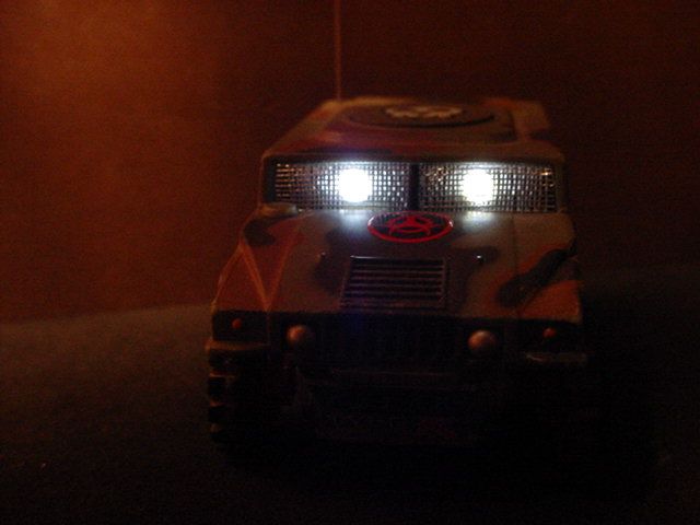
i put these pcb’s in my hummers and hooked up lights to the extra channels, cool little feature!:p here’s a pic of my fancy rc controlled stealth spotties!:8ball:
-
March 10, 2004 at 2:21 am #50004Quote:Been looking at this for a while. At least I now know it DOES work!! I have a NOS design in the pipeline (using capacitor) for some months now. Now to find time…aaahhhh!!
hey ads! you moved on this anymore dude?
ph2t.
-
March 10, 2004 at 2:33 am #50005Quote:uA, what frequencies do they come in… will have to design a little 10db amp for the purpose of an extra 100m or so 🙂
Sorry Trash, I missed this….
They come in all of the ususal freqs, 27, 35, 40, 45, 49, 57Mhz.
I have heard of people using cheap walkie talkies as a carrier transmitter, and running the output of the Txc chip onto that wave.
No range problems after that at all. Little BCG literally drives out of sight.
:)uA -
March 10, 2004 at 2:39 am #50007
Aha!!!!! If you can get two more channels then a 3 speed tranny is possible!!!!
-
March 23, 2004 at 12:21 pm #50255
as micro amps mentioned f1 is available on tomy booster pcb’s, but not connected. i got ph2t to show me how to connect it and it’s simple to do.
for the tomy controller, the same chip is used so wire up a switch to f1 as explained by ph2t. (and you can wire up f2 on a tomy tx which will control f2 on lxx booster rx’s of the same frequency.)in the pic below i’ve marked 5 solder pads with yellow dots which have nothing connected. i’m told the left 2 are for a resistor and the remaining 3 are for a transistor (any ideas as to exactly what sort?). solder a short piece of wire across the 2 pads which are circled in red.

so if you want to connect an led to f1, you would connect + to f1 (circled in red) and – to v- (GND)

if you’re getting the red x treatment http://www.geocities.com/bettyksprivatestash/tomyboosterf1.htmlit’s only 1 extra channel but that’s 1 more than none!:8ball:
-
March 23, 2004 at 12:21 pm #50456
as micro amps mentioned f1 is available on tomy booster pcb’s, but not connected. i got ph2t to show me how to connect it and it’s simple to do.
for the tomy controller, the same chip is used so wire up a switch to f1 as explained by ph2t. (and you can wire up f2 on a tomy tx which will control f2 on lxx booster rx’s of the same frequency.)in the pic below i’ve marked 5 solder pads with yellow dots which have nothing connected. i’m told the left 2 are for a resistor and the remaining 3 are for a transistor (any ideas as to exactly what sort?). solder a short piece of wire across the 2 pads which are circled in red.
so if you want to connect an led to f1, you would connect + to f1 (circled in red) and – to v- (GND)
if you’re getting the red x treatment http://www.geocities.com/bettyksprivatestash/tomyboosterf1.htmlit’s only 1 extra channel but that’s 1 more than none!:8ball:
-
April 16, 2004 at 5:11 am #50786
Okay, I bought 2 LXX perfection cars…supercool cars by the way altho I had to adjust the pot meter a bit but let me go on…there are 2 buttons on top of the controler:
1- Turbo
2- No ideaThese 2 extra channels your talking about is this without the turbo feature included?
I don’t really know how the Turbo feature works altho I understand that in normal mode the motor receives 50% of the battery’ capacity and when the turbo is pressed it gets the full 100%. So this gives me an idea that the turbo feature is also an extra channel.So lets say I put the switch on the back of the controler in the Turbo mode and I use the Turbo channel as an extra channel this would give the car an extra channel right?:
left
right
backwards
forwards
1 extra channel on pin 9
1 extra channel on pin 15
Turbo pin 6 which I also want to changeMy question is: can you use the Turbo feature for another purpose?:)
-
May 17, 2004 at 12:51 am #51467
When I want to use the F1 and F2 channel to hook up two more motors would I need, besides the 2mosfets, also 2 resistors?
-
May 17, 2004 at 2:19 am #51473
nah, you don’t need resistors for the mosfets….. Good design says you should have them there, but you can get away without the resistors.. 🙂 Just connect the outputs from the RX chip to the gate pins on the n-chan mosfets. connect the drain pins to the +BATT and the source pins to the + of the motor you are connecting up. Finally connect the – of the motor to the -BATT. All done!
ph2t.
-
May 17, 2004 at 9:09 pm #51506
Okido! Thanx I’m gonna work on it!
-
June 5, 2004 at 9:11 pm #52067
sorry abuot bringing up a old post but…
can you take aout the turbo button for another channel .. so doesnt that make it 7 channel fwd back left rite f1 f2 and turbo????.. im building a RC plane and want as many channels as need i can get -
July 22, 2004 at 10:48 pm #53868
I’m still wanting to know if it’s indeed possible to use the Turbo pin on the car to fire up someting else?
people told me that the 50% powercut is done internaly in other words inside the RX6C chip…but why is there an output pin?
It is a signal that is transmitted and picked up by the car changin it’s behaviour.
I hope someone can shed a light on this.Thanx!
-
July 22, 2004 at 11:12 pm #53869
i’d say yes. when a signal comes from the chip it’s just that. a signal, just like f, r. left and right. it’s up to you what you use that signal to switch on. in the case of forward and reverse the signals turn on an h bridge. but i’m no techo:8ball:
-
August 1, 2004 at 3:17 am #54103
7 channels?? what??
In the R/C world:
fwd/rev : 1 ch
left/right : 1 ch
elevator up down : 1 ch
ailerons : 1 ch
what more do you want???
-
August 1, 2004 at 3:17 am #54461
7 channels?? what??
In the R/C world:
fwd/rev : 1 ch
left/right : 1 ch
elevator up down : 1 ch
ailerons : 1 ch
what more do you want???
-
August 1, 2004 at 11:06 am #54113
torpedo launch, on off! 5 ch:approve::8ball:
-
August 1, 2004 at 11:06 am #54471
torpedo launch, on off! 5 ch:approve::8ball:
-
August 1, 2004 at 11:02 pm #54129
Baked bean sandwich maker, channel 6 :approve:
-
August 1, 2004 at 11:02 pm #54487
Baked bean sandwich maker, channel 6 :approve:
-
August 7, 2004 at 9:12 am #54251
I know, I know, it takes some imagination and creativity to think of what to do with more (extra) channels.:D
-
August 7, 2004 at 9:12 am #54609
I know, I know, it takes some imagination and creativity to think of what to do with more (extra) channels.:D
-
-
AuthorPosts
- You must be logged in to reply to this topic.