
brushless mr-02 (WIP)
Home › Forums › Mini-Z, Mini-X, X-Mods and other Mini-Scale › Mini-Z, Mini-X, X-Mods – Technical › brushless mr-02 (WIP)
- This topic has 59 replies, 10 voices, and was last updated 16 years, 4 months ago by
ph2t.
-
AuthorPosts
-
-
April 17, 2007 at 12:52 am #12755
I’m currently using the following items:
-HiModel 4711kV 130 brushless motor
http://www.himodel.com/electric/HiModel_4711KV_Brushless_Motor_B2030-8T.html-PN Racing Mini-Z MR015/MR02 RM Motor Mount (Silver)
http://www.rckenon.com/public_html/shop2/catalog/product_info.php?products_id=2397Brushless ESC is still TBA. Most likely a mamba given the issues of size and min 4 cell nimh config.
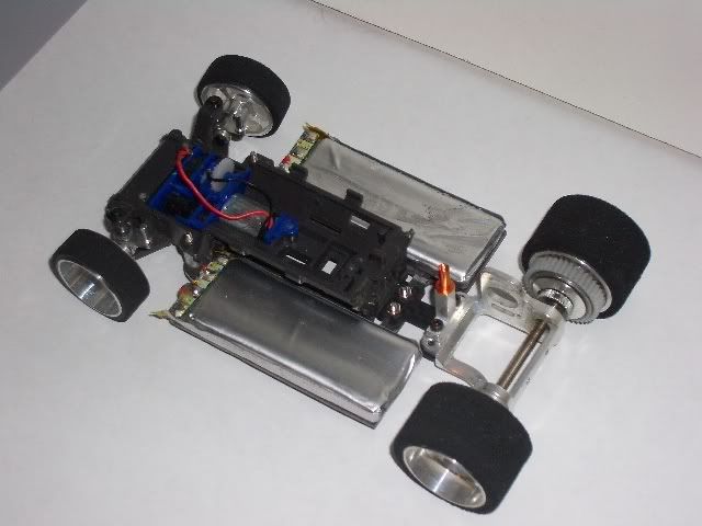
Here’s some pics though to show you that I actually managed to mount the bugger!! It’s a mockup at the moment to make sure everything in the “motor department” fits…. lol…

Setup is tight. Notice where the motor can ends…. lol…

Top view…

I had to modify (hack) the PN motor mount to fit the brushless motor collar in. I took out the top motor screw hole area and also file’d out a lot of “junk” alloy, lol….

Currently it’s got a 12t pinion on there. I drilled the pinion out to fit the 2.3mm shaft. So far so good……May need more space, don’t know yet. It all depends on the ground speed I get. We’ll see…..
Here’s a few step by step shots, showing you the work involved….
First off I had to build up the servo gear area and solder the servo pot and servo motor to some wires ready to install. Notice the green tape insulating the motor can.

Here you can see the GWS PICO controller PCB wired in. Note it uses three servo wires to connect to the PCB. There is also a small 1/8W resistor soldered inline from the original servo, I brought this across in the conversion, there’s heatshrink around it to insulate it.

Now the GWS 40Mhz FM RX is installed. Note the gold plated connectors have been removed from the RX’s PCB. Note that i’ve gouged out some of the internal plastic mounts to allow a bit more room to move things about.

Here’s the mamba-25 being installed. You can’t see the on/off switch wires along with the 3 wire signal connection to the RX. Both of these are on the underside of the PCB.

And guess what, it all bloody fits WITHIN the chassis…..

more to come, soon….. 🙂
ph2t.
-
April 17, 2007 at 3:00 am #60396
wow man thats fkn impressive!!!
i’ve been making a pisspoor attempt to do that same over the last few months. biggest obstacle is that i don’t have an FM transmitter. doesn’t seem to be much point in doing it AM. plus there aren’t many cheap receivers available on ebay!
are you planning on rewinding the motor to get more speed? i always found that a major drawback. if you were running 4 cells max rpm would be a little under 30,000. thats kinda sucky
how is the pinion you drilled out going? are you having any trouble with it not being exactly centre anymore?
some awesome work man :topstuff:
-
April 17, 2007 at 4:15 am #60397
thanks dude 🙂
I can’t rewind the motor, it’s an inrunner brushless that is press fitted together so opening without killing it for me is unlikely, lol…
you need to go FM. apart from the novak xxl (i think), there is virtually no micro 27mhz am receivers out there. I looked, lol…. I bout the Sanwa 40Mhz TX from rcmart. bought the receiver and micro crystal from http://www.aircraft-world.com .
one you de case and modifiy stuff, you’d be amazed how much you can cram into one small place, lol…
it’s actually pretty fast, pulls around 30kph on the tamiya speed checker on 4 cells AAA and 50kph on 6 cells. still got lots to do though….
I could even go to a hotter motor, right up to 7800kv which would be insane. 🙂
-
April 17, 2007 at 4:34 am #60399
:smiley3:
damn impressive. you planning on using lipo’s?
-
April 17, 2007 at 4:37 am #60400
7800kv? you may have just got me interested again…:D
-
April 17, 2007 at 6:39 am #60401
done some research and the Feigao’s only do a max 50,000 rpm.
so i guess running a lipo setup max voltage would be around 8v which would mean the highest safe rpm/v rating would be 6240rpm/v.although what i’m not sure of is if the actual top speed under load. maybe you could go a little higher if the 50,000rpm limit is set by the bearings. i have no experience when it comes to this…
-
April 17, 2007 at 6:47 am #60402
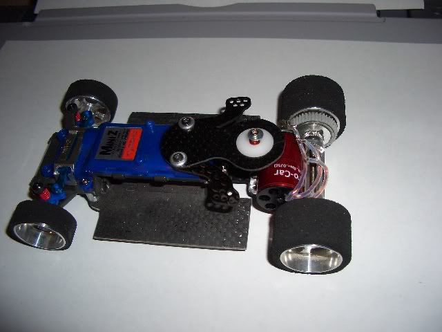
OK. Gots more done today. 🙂
I got the setup completed in it’s first revision. lol. nothing is final yet.

On 4 cells it is quite “fast”. It matches a typical PN S03 setup for an ’02. Steering is suprisingly good and consistent. I definately noticed the weight though and being an RM setup it’s even more pronounced.
Current gearing is 12t pinion, stock gear diff. I get 30kph on the speed checker on 4 cells. 50kph on 6.
At first it bounced around on the concrete like a crazy bugger so I’ve installed an oil shock to help dampen that. I may change h-plates as well. I’m running a medium thickness one at the moment. We’ll see….
The oil shock is sitting a bit too high for my liking at the moment. I got to get the right bits to fit, lol…

You can see the mamba-25 taking up pretty much all of the “penthouse level” space within the guts of the ’02 chassis, lol…. the poor GWS servo PCB is wedged in beween the mamba and the steering motor, poor bugger, lol….

And here’s a rear shot showing how this bigarse brushless motor sits, lol…

More to come, video to shoot soon, hopefully!!!
lipo is in the mail, lol…
ph2t.
-
April 17, 2007 at 11:26 am #60403
Thats sweet Ph2t !!! I wish I had some brushless stuff to play with !!!
-
April 18, 2007 at 3:25 pm #60428
What I’m finding is that lack of dampening is the issue. The “springyness” of the h-plate is the main culprit. Couple this with the weight of the motor and the rear end just bounces around. Even still with the oil shock although it’s less.
I’ll try a spring on the oil shock and may install the damper shock system with the oil shocked piggy backed on top. I’ll see how I go. I think though at the end of the day, on anything but RCP, this setup is not gonna get long term traction. We’ll see, I need to work on the rear end a bit more to lessen this problem.
If I put some weights up the front, will this help at all? Not in the traditional case argued earlier in this thread but one to stop the rear “bouncy boucdy” that’s happening…..
On a seperate note, I got futher finding an ideal pinion for the 2.3mm shaft. I’m now got installed the GPM pinion for the Half8 stock motor (which is Kyosho 2.3mm !). Got rid of the foil lining the shaft so it’s a true fit now. 🙂

The ball diff will help I reakon with smoothing out the ride. Some of the “bouncy bouncy” is partly to do with the gear diff and it’s no mucking around takeoff, lol….
I’ve also got to put some camber steering knuckles in, I’m running stock at the moment on Ezno offsets. The offset will change eventually depending on which shell it goes into…..
Anyways, here’s a list of pinions that will work with 2.3mm shaft brushless motors.
GPM (#TMIF012T) Titanium Motor Gear (12T) -1pc (TMIF012T)
11T Alloy Motor Gear (for 380 Motor) (Y–021)
DO NOT BUY THESE! (even though it says 2.3mm shaft, the pitch on the gears is a bit wider than the spur gear)
MB4 Alu. Motor Gear – 12T (for 2.3mm rotor) (MB-017)
MB4 Alu. Motor Gear – 14T (for 2.3mm rotor) (MB-018)And on it goes……
-
April 20, 2007 at 3:45 pm #60446
OK. I found that if I use the stock kyosho mr-02 hplate instead I have now reduced the bouncing a fair bit and made it more drivable in the corners.
The cf hplates are too rigid to allow the oil shock to dampen properly. With the plastic hplate though it can flex more and allow the oil shock to do it’s work.
Also, once in the shell the rear end fits with no issue!

Here’s another photo. i’ve put on the wheels from the audi autoscale (30deg ATOMIC groove on the front, soft GQ foams on the rear, trued of course)..

And here’s one with the shell on. You’d never know she was brushless….

I also full rebuilt the oit shock and put in ATOMIC 1000 mini-z shock oil. All my other grade oils were just too thin. Now the oil shock finally dampens earlier than before on the older oil.
So, I’ve got a few other things but for most of it this setup is now done. 🙂
-
April 20, 2007 at 3:58 pm #60447
that is wicked !!!
-
April 24, 2007 at 8:01 am #60495
nice work man! can wait to see some action shots.
which LiPo cells did you go for?
and is there any reason you didn’t use the pinions available in the ausmicro shop for 1/16 buggy? checked mine and they seem to mesh alright.
-
April 24, 2007 at 12:58 pm #60497
how much longer before you get it running? would mind seeing in action
-
May 2, 2007 at 12:43 pm #60566
@klims 225599 wrote:
nice work man! can wait to see some action shots.
which LiPo cells did you go for?
and is there any reason you didn’t use the pinions available in the ausmicro shop for 1/16 buggy? checked mine and they seem to mesh alright.
those pinions are 2.3mm shaft or 2mm? I used Hyperion 300mAh lipos in the end, 20C!!!!
OK, here’s another update.
On 4 cells it can be a little sporadic in it’s throttle if pushed hard. Using the mamba esc settings to reduce the power to the motor seems to help with this. Also, putting the cap back on helped with smoothing things out.
Of course the original has gone the way of the dodo and has a surface mount capacitor put in it’s place.

The cap I’m using is a 330uF 6.3V cap. Yes it is below the operating voltage for the lipo but it works. You can push V ratings on caps a bit, done it stacks over the years, but don’t expect ’em to work EVERYTIME, just 99% of the time, lol…..
Making it fit was a challenge, like everything else in this anorexic chassis……

So it’s all good now.
I also looked into adding an extra 3 pin port to plug the Mamba-25 external USB link (CastleLINK), but it would of involved including another switch (to isolate the mamba from the rest for the setup for programming purposes) and socket so the space ran out pretty quickly. Esentially I’ve had to learn to program it via the “beep” method, lol… Painful at first it was but after a while I got used to it.
Finally though I got some freakin’ video down! 😈
Brushless mr-02 AVI
8.7MB, DivX, AVI format, 480×272.(You need DivX/XViD codecs to view this vid, MPEG4 ftw!)
Enjoy!
ph2t.
-
May 2, 2007 at 3:00 pm #60569
looks pretty sweet man, looks as it has got some nice take off too. how long do the lipos last in that??
…….well done
-
May 2, 2007 at 10:04 pm #60574
how you managed to squeeze a lipo pack thats dimensions are 51X23mm into a space thats 48(at best)X21mm baffles me. you never cease to amaze! lol.
those pinions are 2.3mm shaft or 2mm? I used Hyperion 300mAh lipos in the end, 20C!!!!
thats an interesting question actually. got my Feigao in today so i tried out the pinions and was quite shocked at what i found. here is the list…
1 X 16t 2.3mm
2 X 13t 2.3mm (different colours)
1 X 12t 2mm
1 X 15t 2mmno idea what happened there…
looks pretty fast. i bought a 6240kv brushless to try myself. maybe i went a little to far…
was there any reason you went for the RM setup and not MM? was it a space thing?
maybe someone else can help with this question…. which handle better?excellent work mate!!!
-
May 3, 2007 at 11:46 am #60587
best soundtrack ever…
I’ve been singing that song since I last heard it over 20 yrs ago
oh yeah – stoopidly fast small car too!
-
May 5, 2007 at 1:11 am #60592
I went RM due to space considerations. The motor is just too large for MM. If I could pull it off it will result in the motor sitting so high the roll on the chassis would be too much.
Once the li-po cells are removed from the actual pack they become a lot shorter, making it feasible. Although the battery tabs in the chassis do make it a tight fit.
So the feigao you got is a 2.3mm or 2mm shaft?
-
May 5, 2007 at 5:27 pm #60594
I went RM due to space considerations. The motor is just too large for MM. If I could pull it off it will result in the motor sitting so high the roll on the chassis would be too much.
i never thought of that. i contemplated destroying my MM to fit it in but went for the RM. its a much nicer fit with less custom parts to be made
Once the li-po cells are removed from the actual pack they become a lot shorter, making it feasible. Although the battery tabs in the chassis do make it a tight fit.
i had no idea about that. do you know this to be true for all packs? so do you bend up the metal bit on the lipos that the terminals come out of to make it shorter? i mean that bit thats not actual cell.
So the feigao you got is a 2.3mm or 2mm shaft?
its a 2.3mm. this is the beast. was really impressed with the price:D although i have never seen such over the top packaging. the UPS box was about 30X25X10. f@#ing ridiculous!!!
-
May 6, 2007 at 2:52 am #60597
-
May 6, 2007 at 9:11 am #60598
wow, they look pretty snazzy man. including the fact that they’re part of those new lipos out there that can charge at 2C. good stuff.
As for lipo packs, yes, all the ones I have encounded use the void where the tabs are to put either wood or plastic to strengthen the area and join. You can bend thses up (once removed from the pack of course!) and get an extra 3-4mm of space back.
See the attached pic. 🙂
-
May 6, 2007 at 9:45 am #60600
lovely!!!! just picked myself up 2 of the 40c(burst) lipo packs for $45AUD delivered.
do my eyes deceive me or do you only have 1 cell per battery compartment? i thought you had bee squeezing in 2 cells this whole time!
nice work on a whole. i’ve just finished ordering all the parts i’ll need to get my brushless up and running.
been having some trouble with the servo though. bought a 5g servo i tried to reconfigure to the mini z servo setup but no luck. i don’t think it was made to run with such a strong motor. the servo just shook from side to side like jitters but WAY bigger. picked up a 9g to try out because from what i could tell the motors are about the same size that the mini z runs. i must admit though i didn’t do the 1/8W resistor. i used the pot that came with the servo. did you have any problems getting the servo running? -
May 6, 2007 at 10:27 am #60601
Nah mate, the servo is just fine. The key is in the feedback potentiometer in the servo you choose to butcher/adapt. The one I used (GWS Pico Servo) uses a 5K pot in the feedback arm so it was more suited to the 5K pot that’s in the miniz steering assembly.
You can try and put a small valued resistor in series with the motor to reduce the current (and therefore speed and torque) that the servo motor responds with. This may work for you.
The resistor in the pics comes with the GWS PCB, I didn’t add it. Although this is another trick that can be used to help get the correct slew (ie: side to side motion with the full extents) for feedback. Betty knows about this, he did something similar in another project (which I forget at the moment).
Yes, 1 cell for compartment. So it’s only a 7.4V 300mAh pack. The funny thing is though that the runtime is still excellent because the larger brushless motor draws less current buyt delivers more torque than it’s 130 sized brushed counterparts.
My AAA’s aren’t even warm after a long run!
This may change though when I get my new brushless motor in from Razor motors. Here’s an excerpt from a postmade by another member (CowboySIR) on another forum I’m on and the same thread there:
Quote:I think i may have found something for you to take a gander at ph2tty…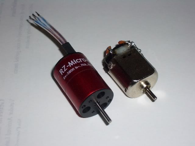
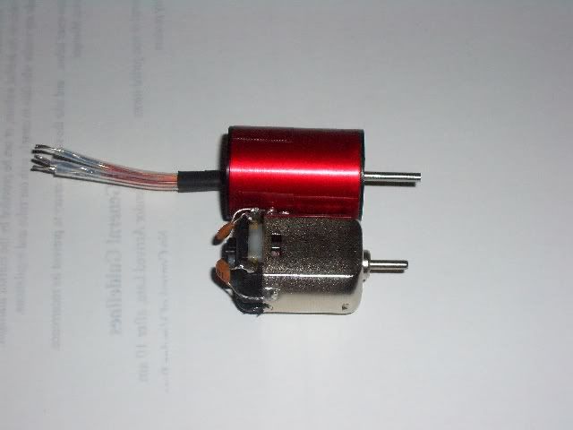
The company is called Razor Motors out of Santa Barbara.
Diameter:19.5mm
Length: 26.8mm
Shaft:2mm 😈
Kv:5800
weight: 25gramsI compared size to a standard 130 motor and it’s almost exactly the same length and width(compared to the fat width of a 130). On the can I’m having trouble deciphering the “0.7A”…I’m guessing the no load current?
I hopefully will try a similar construct…and I hope to find this baby fits an MM mount.
edit: check the 130 BL thread for a fitment comparison.
can’t wait for this bugger to come in…….
-
May 7, 2007 at 1:55 am #60609
that is nuts!!!! which one did you get? they are a bit pricey. might have to save a for a few weeks on my student wage lol.
My AAA’s aren’t even warm after a long run!
correct me if i’m wrong, but would that mean you are running close to 2A constant? if so thats nothing. what kind of run time you get out of the lipos? the feature i’m looking forward to most is voltage cutoff on the ESC.
i’ll see how i go with the servo. i’m starting to think i should have paid more attention in some lectures… i’ve done slew rates! even modelled systems with feedback, which i guess is a servo. damn my slackness!
-
May 7, 2007 at 2:15 am #60610
lol, same here dude, was the same for me at uni. did BE Elect & Comp Sys at Monash and the only real application I’ve had for the elec eng bit over the years is this shit, lol…..
-
May 7, 2007 at 4:03 am #60612
BE Electronics? now i see where you get the skills from… i’m doing BE mechatronics & comp science. i’m not so good at electronics but have always been interested, and can’t see myself as a mechanical knob so what better option than to combine the two!
back on the topic… you planning on a MM version with the new brushless?
-
May 7, 2007 at 4:11 am #60613
yes, again from Cowboysir from GSR.
Quote: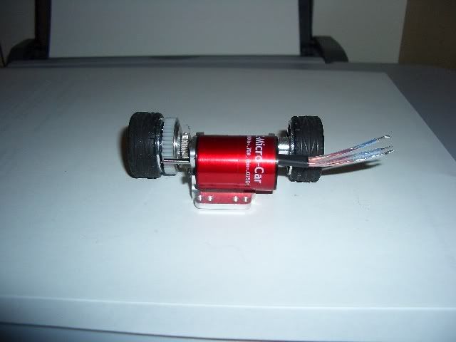
aparently it all fits, you need to mod the shock mount though since the motor gets in the way.
the other benefit is that it’s lighter a well.
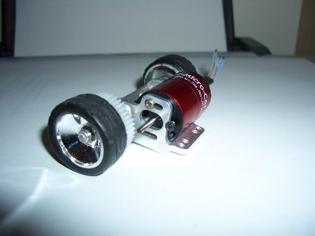
it’s the RZ MICRO model:
Quote:RZ-Micro Car
The RZ-Micro-Car is designed for micro RC cars like the HPI Micro RS4. the motor uses the big block mounting plate, with very minor modifications. You need to drill out the single hole to 5/32.Kv: 5650
Io: 0.70A
Rm: .075
Weight: 27g
Length:
(w/o shaft) 27.8mm -
May 7, 2007 at 5:33 am #60616
oi!
I’m a mechanical knob ahahahaha
-
May 7, 2007 at 6:28 am #60617
lol i was making a pretty broad generalisation. in particular i’m reffering to one group of mechanical engineers at uni that are the biggest and loudest bunch of rednecks. but i’m sure your nothing like them…
-
May 7, 2007 at 10:25 am #60619
it could be worse, he could be civil. lol…
-
May 7, 2007 at 12:12 pm #60620
lol i guess…
so i tried all the tricks i know, and then some of yours but still can’t get this fkn servo to work! best i could get was it to stay centre and then move either left or right, but with no accuracy. kinda no point in having a prop setup lol. i guess i’m gonna have to dish out the cash and get the GWS pico you have. i guess at least that way i know it will work!
-
May 9, 2007 at 2:24 am #60631
hey PH2T had a question for ya about the over voltage on the cap. was speaking to our electronics guy at work as i was looking for a lager cap for my ESC too and he lost it when i told him i was gonna go over voltage on it. he is a bit old school but he says that you should always go much lower than the rating or it could explode. you ever had a tantalum cap explode? i know from experience that electrolytic go off like firecrakers if overheated. nearly took out my eye! was great fun though
-
May 18, 2007 at 10:49 am #60678
so my GWS pico came in and after a few hours trouble shooting i found that i need to run 10K resistor in line with the motor to get it working. not sure if it makes a difference but the servo motor i’m using came from an iwaver. my receiver and crystal are in the mail so i should have my beast up and running in no time.
also though i would mention that one of the fitter and turners from the workshop at work was able to plug then re-drill one of the pinions available in the ausmirco shop for me. now it fits a 1.5mm shaft so my 12mm feiago is also in the mail:D . i plan to use it in a MM version. way cheaper than the razor brushless.
that for the help with the servo PH2T
Andrew.
-
June 30, 2007 at 1:39 am #60803
Hey Guys,
Just joined the other day to get some spider info and I thought I’d show you my progress on my BL conversion. I’m at the bench test phase(working on the setup before I decase and hardwire the servo/esc leads) but on four cells this thing is pretty fast. i don’t have a comparison yet(no track where I live and its raining) but here are some photos of fitment to an F1 alloy motor pod and the crappy bench test vid.

http://s13.photobucket.com/albums/a258/CowboySiR/?action=view¤t=benchtest.flv
I’ll update eventually…
-
June 30, 2007 at 3:31 am #60804
nice work :thumbs_up:
what servo did you go for?
-
September 18, 2007 at 1:34 am #61130
OK, bit of an update now. Hopefully I will have this running within the next couple of days….
Mid-Mount brushless is on it’s way!!

The motor is an RZ-300 brushless motor by Razor Motors.
You can purchase it from here: http://www.neumotors.com/20061222/Razor%20Motors.htmlThe specs of the motor are as follows:
– 2mm shaft (yay!)
– 4900Kv Rating
– 27g weight
– 28mm long x 20mm dia.Here’s another picture showing the fitment in the PN Racing (low CG) MM mount.

It’s using an 8t pinion at the moment. I’ll see how it goes with this. May be a bit
slow on 4 cells but we’ll see. The Kv of this motor is higher than the first version so
that should help offset some of my speed concerns.I had to do a fair bit of filing on the alloy to get the bugger to fit.
I did manage to get both screw mount holes in this time so it’s nice and
stable (unlike the first RM version that only had the single screw mount!).I managed to keep all the alloy in one piece without breaking the structure in any
part. This was a risk associated with going down this path.I’m just happy I got the buger in. Next step is to wire it up to the chassis and
mount the rear assemble and test it out!My only concern is that this particular brushless motor has a fair bit of drag when
off. I will see if the mamba-25 esc can help me with this, or if it’s just a case setting
the throttle neutral point on my TX.More to come! With a new (poor poor) shell too!
ph2t.
-
September 18, 2007 at 3:14 pm #61134
OK. Finally got this new motor into the chassis. The motor has a lot of drag, I think it was originally intended for a small heli conversion, not sure exactly. Given the drag I needed to make sure that my TX was set to +1 for throttle when in the neutral position. I seem to of been lucky, at this setting it’s not enough to go forward constantly but enough to stop the drag from kicking in at 0 throttle.
Took it out for a spin on the concrete driveway and it works well. So happy to be back in a MM config again and with a motor now that ISN’T 6 times heavier than a stock 130, lol…. (see previous RM attempt).

The acceleration is quite strong, faster than my 36t pattern wound motor I’ve got from flash (best off the mark accel motor I have, and I’ve got lots!). This is to be expected though. The Razor 300 is meant to be a replacement for a Speed 300 sized motor so you can see that it has some balls.
I put on a 9t pinion and on 4 cells the speed is comparable to the PN saber. It’s just what I wanted. The high 4900Kv rating of this particular motor is a nice sweet spot (on 4 cells). As I mentioned very early on in this thread, the goal is to make a comparable racer based on brushless, not to make a crazy speed machine (did I just say that? lol…..).

Anyways, next step is to fine tune the setup. I need to get the oil damper back on, may change to a thinner CF h-plate, rebuild the front end (concrete dust is a @#$%^) and FINALLY get that lovely MM shell I’ve got for it (RIP audi DTM, lol….).
More to come!
ph2t.
-
September 18, 2007 at 9:39 pm #61135
coolness! finally nailed that sucker!:beer:
no more bouncy bouncy:D :8ball:
-
September 18, 2007 at 10:15 pm #61136
Yeah, all I needed was to have another kid to find the time, lol…….
-
September 19, 2007 at 1:50 am #61137
nice work mate! really impressed with the size of that thing.
are you getting killer long run times?
-
September 19, 2007 at 4:17 am #61138
well done on such a neat conversion 😀
-
September 19, 2007 at 10:45 am #61139
@klims 226354 wrote:
nice work mate! really impressed with the size of that thing.
are you getting killer long run times?
at the moment I’m still er, um “debugging” it, lol….. Seems to want to cog like there’s no tomorrow. Went to gaycar today and bought some small as dil switches and some plugs, gonna make a connector to allow me to plug int he USB interface so I can program the ESC via the PC. Up untill now I have been programming the ESC via the beep/TX method but the full command set is only avail via the USB. To do this the ESC must be taken out of circuit from the rest of the ‘tronics (RX, Servo). It doesn’t work to try and program the ESC when you have it still conenected to the RX.
Just gotta find the bloody space to do this in!
-
September 19, 2007 at 10:46 am #61140
@Dangerous Dave 226355 wrote:
well done on such a neat conversion 😀
ta muchly!
-
September 19, 2007 at 10:23 pm #61141
OK, I’ve started on the setup that will enable me to program the mamba-25 esc without haveing to remove it. Pretty much it involves a simple switch that is put in between the ESC and the RX. This way when I need to program the ESC I just switch it out of circuit and that will ensure the USB program inteface all works OK.
Here’s a simple diagram of what I’m talking about:

The challenge is finding a switch small enough. I decided to hack an 8 pin DIL switch by chopping off one of the 4 SPST switches and leaving it with 3. One switch for each wire (GND, V+ & Signal). I then soldered this onto a small 3 pin terminator strip that I had also cut down to size. The goal being to mount it up the front somewhere….. That bit is still being worked on….

More to come…..
-
September 20, 2007 at 12:40 am #61142
looks like you should have just used a header pin lol
why not jam it in the place where the crystal/switch used to be? seems like a lot of unused real estate.
-
September 20, 2007 at 2:02 pm #61145
Won’t fit down there. Keep in mind I need to be able to switch the ESC out of circuit to enable the USB program interface to work. I tried with the ESC connecte to the RX and it’s a no go….
-
October 4, 2007 at 11:24 pm #61228
I’ll post here my question cuz I’m going to do something similar with my Iwaver…
Do you think that a 25A brushless esc could be enogh for a 130 class model upon 6500Kv,using 4,8V setup?
And,most of all,I’ve seen that many brushless esc(mostly the ones for airplanes)say the work on 6-x cells,but will the work with a 4 cell setup?
Thanks!PS:
This BL mini-z is great,but I think you should have left the possibility to unplug esc and servo from the rx(I’ve purchased the same one rx 😀 )
I’ll probably do this positiooning the rx vertical in the center chassis,with the pin size down,so I’ll put the wires in that dead space behind left and righ cells,and the esc in your same position(of course I’ll use a different esc)I want a video with that 300 class,body-annhilator motor.
-
October 5, 2007 at 5:37 am #61231
dont bother with an ariplane esc mate. i tried and it was pathetic! they have horrible throttle response, and they WONT WORK ON 4 CELLS! no matter what the ebay description says, its wrong. i bought 2 from ebay that said 4 cells and neither work. just go for the mamba. its expensive but worth it.
-
October 9, 2007 at 3:02 pm #61240
I didn’t think it was worth starting another thread(since I’m just creating a variation of ph2t’s design) so this is where my Brushless Mini-Z is heading…
I had to scrap the F1 design because I couldn’t get the body to snap down over the RX’s cap towers. I’ve switched to a 1/24th conversion and staying for the most part with guidelines similar to ph2t’s….my only variation is keeping the RX pcb intact on the exterior so I can mange programming without having a shunt in the lines. I’ll also be able to use the RX for other 1/18th applications.
This is my status…note the custom Li-Po tray, custom disc damper plate and 1/24th scale Mercedes CLK-GTR body.
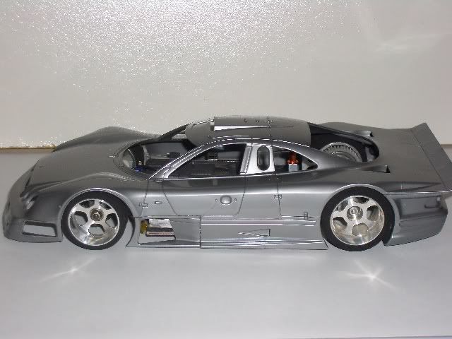
I think this’ll be some fun to run.:D
-
October 9, 2007 at 10:54 pm #61241
@CowboySiR03 226407 wrote:
I didn’t think it was worth starting another thread(since I’m just creating a variation of ph2t’s design) so this is where my Brushless Mini-Z is heading…
I had to scrap the F1 design because I couldn’t get the body to snap down over the RX’s cap towers. I’ve switched to a 1/24th conversion and staying for the most part with guidelines similar to ph2t’s….my only variation is keeping the RX pcb intact on the exterior so I can mange programming without having a shunt in the lines. I’ll also be able to use the RX for other 1/18th applications.
This is my status…note the custom Li-Po tray, custom disc damper plate and 1/24th scale Mercedes CLK-GTR body.
I think this’ll be some fun to run.:D
The body is WOW!!!
which esc are you going to use?
I noticed that GWS is selling now the pico rx with horizontal pin,so we could use the dead space under the esc to fit esc and servo plugs without remove rx pins and solder the wires…I’m developing(veeery slowly)a similar project on my iwaver… -
October 29, 2007 at 10:30 pm #61246
Just a question to ph2t: don’t you have any interference trouble due to the esc close to rx?
Thanks! -
October 30, 2007 at 7:04 am #61238
that looks HOT!!!
how do you plan to hold in the lipos? you tray doesn’t seem to have and “crash” protection. it would suck to see 40+bucks of lipo rocket out the front window if you hit something…
-
November 1, 2007 at 12:10 pm #61191
@jollyboss 226476 wrote:
Just a question to ph2t: don’t you have any interference trouble due to the esc close to rx?
Thanks!Not at all mate. Be it my FM mr-02 “brushed” car or this brushless version. Either setups don’t get any interference.
-
November 1, 2007 at 12:12 pm #61192
Just a warning to those who want to use brushless motors in their Z’s. Get fully %100 sealed ones. My very @#$% expensive @#$% motor, siezed the @#$% up on me due to @#$%^ dirt getting in those !@#$% air vents at the rear of the can…..
arghhhhhhhhh…….
-
November 1, 2007 at 12:34 pm #61193
are feigao ones good?
see Himodel..
Anyway I have another question:which brand of AAA are you using for brushless?
I was attracted by the 750 intellect,but I’d like to hear more voices about. -
April 15, 2008 at 5:17 pm #61649
Well. I figured out the problem and it was more of a design one than anything else.
This newer Razor Motor’s brushless motor I tried in the MM config had too much curent draw for 4 cell AAA to run on effectively.. Even my best set of AAA’s would result in the motor “dumping” after about 30 seconds of use.
Now this wouldn’t be a problem, just run it on the 400mAh 7.4V lipo “saddle pack” and it’s fine. Although shithouse run time. Besides I really want this conversion to run on 4 AAA’s. So there goes that idea.
Also this motor has an incredible amount of magnetic drag when not powered. Some brushless motors have this, some not. This is killa in an ’02 chassis. you need to be able to coast around corners under no/little acceleration. you can’t do this with this motor.
With the first motor I tried though, I can! 🙂
So time to revisit that first motor. I always thought it was too big for a MM setup (hence the RZ motor purchase) but given that I was now looking at an incredicbly hacked up PN racing alloy MM mount (for shame!) I thought I would give it a try.
Here’s a few mockup shots. Ain’t final yet…

The area circled below is the space I hope to make up. This will give clearance to an incredibly agitated left tyre, lol…

More alloy hacks, everything alloy inside of the yellow lines has got to go!

Here you can see all the offenders….

So, once this is mounted, I can put the top plate on and then figure out a way to install a shock 🙁 Don’t like my chances…Fingers crossed!
ph2t.
-
February 23, 2010 at 9:50 pm #40900
Check this motor out:
http://www.allerc.com/product_info.php?products_id=734The best bit it is the 2mm shaft!
Mine just came in today. Its not exactly as it looks in the photo. The main difference is that the can is flat front and back. This is a bit annoying because the motor doesn’t slide into the motor mount recess like ph2t’s first motor.I mounted it in my RM setup and the motor just barely touches the left wheel. One shim on that side fixed it.
Haven’t had a chance to run the motor in my setup yet. Fried my mamba the other day :-/ Once I get it all working again I’ll post some more info.
-
March 2, 2010 at 5:11 pm #25987
I am in the process of modding my car. I have already got the esc to work with my DX3S. I am having problem with the servo. What I did was use the control board from a hitec hs55. Wired all the 5 wires.
But when I turn the on the radio, the steering goes to one side. I cannot seem to turn it the other way. I know the pot is centered. So, I removed the
motor and tried it without the pot turning with the gears. The motor does turn clockwise and anticlockwise when I turn the steer on my radio. I see you mod pics that there is a resistor on the servo controller board. Where is this connected and how do you calculate the value needed.Thanks
-
March 5, 2010 at 8:23 pm #21469
I had exactly the same issue at one stage. Fixed it by putting resistors in series with motor to reduce the amount of current it was getting. I started with 10ohm and kept adding till it was working properly.
The resistor that is on the servo wires was already there when the servo was pulled apart.
Do you know for sure that the hitec servo uses a 5k pot? Because if not this may also be your issue -
March 6, 2010 at 4:53 am #21550
I checked the pot value. It was 5k. But what I did was went ahead and opened up the spektrum micro servo and placed that. It worked right away. There is a slight centering issue but I believe i can fix that by adjusting the trim resistor on the servo pcb itself. I’ll post some pics when I get a chance.
-
-
AuthorPosts
- You must be logged in to reply to this topic.