
iwaver pcb in a zz mt, the cheats method!
Home › Forums › Bit Char-G, Digi-Q and other Micros › Bit CharG and Micro Radio Controlled – Technical › iwaver pcb in a zz mt, the cheats method!
- This topic has 15 replies, 4 voices, and was last updated 21 years, 5 months ago by
biohazard.
-
AuthorPosts
-
-
December 10, 2004 at 1:38 am #10278
the biggest mental obstacle in making my zz monster truck propo was installing a servo for the steering. then i thought why bother? the pcb runs a motor so i removed the servo motor and connected the mt steering motor. without the servo pot the motor would run in one direction constantly so i used a resistor in it’s place.
the servo pot on an iwaver is 5k ohm so i aimed for a value somewhere in the middle. i found a 3.3k ohm. after centering all the trimpots i wound up with perfect steering in both directions.
if you observe a disassembled servo that’s hooked up you’ll notice the motor has about 2 or 3 steps in it’s speed. so when i turn a little, the motor gently turns the steering and turning hard makes the motor spin at full speed. this coupled with the return spring provides about 2 fuzzy steps of steering each way. i tend to turn at full lock in the rough anyway so it’s fine with me.
the throttle control is fantastic! even with the orange motor/gear combo i can lift the front from a standstill or crawl along like a snail with everything in between. i installed 3 x 200mah nimh to power it along:8ball:
-
December 11, 2004 at 4:35 am #23864
do you have any pictures of this mod yet?
-
December 12, 2004 at 4:57 am #23786
sorry none yet. but i don’t think they’re needed, it’s just too easy!
step 1: tricell (or quadcell) or lipo your mt
step 2: remove the stock pcb
step 3: solder the motor wires to the motor terminals on the iwaver pcb
step 4: solder the power wires to the iwaver pcb
step 5: solder the steering motor (on the monster) wires to the same place that the servo motor was attached on the iw pcb
step 6: remove the servo pot (variable resistor) from the iw pcb and replace it with a fixed value resistor with a value somewhere in the middle of 0ohm – 5kohm
step 7: center the steering trim on your tx and fiddle with the steering trim on the pcb until it is centered and not twitching much
step 8: go back to the steering trim and adjust it until the steering stops twitching.and that’s it! you will still hear occasional twitching and when you pick it up the steering moves a tiny bit as a result of this twitch but on the ground it makes no difference.
all i wanted was propo throttle, i expected the steering to be all or nothing like a bit but i’m amazed at how well the whole thing turned out. seriously do it, and you’ll see what i mean:smiley2:
i will get pics when i get hold of the camera:8ball:
-
December 12, 2004 at 11:06 pm #23775
damn man i want pics!!!!!!!!!
im interested in this mod i got a spare iwaver board doing nothing LOL
-
December 14, 2004 at 7:17 am #23740
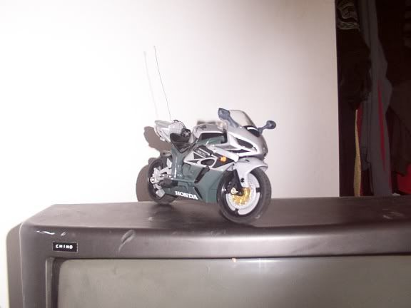
awwright! here’s ya pics! here’s the insides

the pcb sits a little high due to the tri cell

but not so high that the body won’t fit:8ball:

-
December 14, 2004 at 11:56 am #23737
okay now a vid!!!!! :p
-
December 14, 2004 at 1:30 pm #23738
yeesh! there’s just no satisfying you is there!:D:8ball:
-
December 14, 2004 at 3:40 pm #23728
the stock steering motor is pretty weak so i used a bit motor (red zz 2.1) in it’s place and the steering is finally strong enough. i tell ya, so much fun for so little work!:8ball:
-
December 14, 2004 at 10:22 pm #23686
what batt’s are you using man?
-
December 15, 2004 at 2:46 am #23681
it’s a tri cell using 200mah nimh:8ball:
-
December 15, 2004 at 10:20 am #23670
ahhhh okay den sounds cool den.
interested in doing this job for me LOL
-
December 16, 2004 at 5:28 pm #23613
betty
what do you use to charge those bad boy 200 batteries -
December 16, 2004 at 7:18 pm #23611
i use my nicad/nimh charger for everything. does 1 – 10 cells up to 4 amps:8ball:
-
February 7, 2005 at 5:52 am #21498
betty. the resistor thing u did to the iw pcb (for none propo steering) is it posible to do this to an xmod pcb? if so can u show me how.
i wannah put an xmod pcb ina $20 street bike ive been messing with.
and heres a thread i posted i while on it
http://p221.ezboard.com/fxmodrcfrm17.showMessage?topicID=1597.topicEdited by – chino on 07 February 2005 00:53:30
-
February 7, 2005 at 11:22 pm #21485
well i’m no techo but this is what i would try first:
the variable resistor (servo pot) is the same value in the i waver and the xmod, 5kohm.
as i’m thinking this up it seems kinda dodgy but here goes.
find a 2.5kohm fixed resistor (or the nearest value) and connect 1 end to the wire that went to the middle terminal on the pot (common). then solder the other 2 servo wires (the outer 2) to the other end of the resistor.like i said, i’m not too sure how to go about it, i dunno about the technical stuff. i just got lucky with a hunch on the iwaver:D
you should wait until someone who knows what they’re on about confirms this, the chance of frying something is too great!:8ball: -
February 7, 2005 at 11:51 pm #21496
hey its better than nuthing so. ill try it, i got so many xmod pcbs
-
-
AuthorPosts
- You must be logged in to reply to this topic.