
my “Woah Nelly!” Turbo….
Home › Forums › Mini-Z, Mini-X, X-Mods and other Mini-Scale › Mini-Z, Mini-X, X-Mods – Technical › my “Woah Nelly!” Turbo….
- This topic has 381 replies, 40 voices, and was last updated 18 years, 10 months ago by
jollyboss.
-
AuthorPosts
-
-
April 20, 2004 at 12:32 am #12104
I m just sick and tired of frying my fet stacks.

So I decided to make an external turbo. I wanted to make something
worthwhile in the performance side so I looked for the lowest resistance
MOSFETs I could find.I ended up with two candidates:
NTD110N02R – N Chan MOSFET – http://www.onsemi.com
IRF7425 – P Chan MOSFET – http://www.irf.comSearch those websites to get their respecte datasheets.
These two lil buggers put the “Woah” in my “Woah Nelly” turbo. The all
important on resistance is mega low.To put this into perspective you need to understand the amount of resistance in the normal IRF7389 MOSFETs that are used when “stacking” MOSFETs. Below are the values that I pulled from the datasheets for all the MOSFETs involved.
You need to add up the total resistance (less motor resistance) in the path that the motor current travels in. You then have the following values.
IRF7389 MOSFET
nchan 30 mOhm + pchan 75 mOhm = 105 mOhm
Woah Nelly MOSFETS
nchan 5.0 mOhm + pchan 6.0 mOhm = 11 mOhm
That s a ratio of over 9:1! This means (theoretically) that these MOSFETS will have the performance of a 9 stack of IRF7389 MOSFETs. That s nuts!
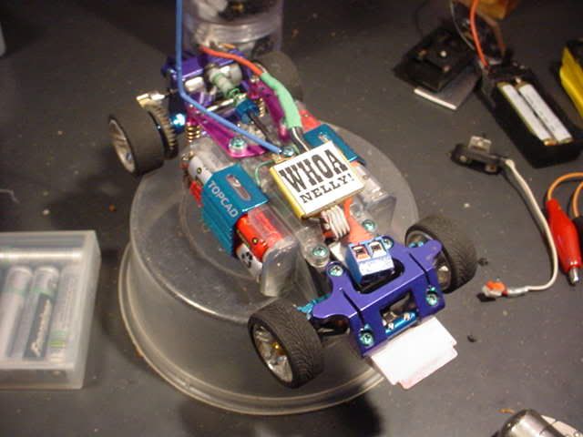
Woah Nelly v1

Woah Nelly v1 hooked up to the RX pcb

NOTE:You need to remove the drive train MOSFETS (be them stock or otherwise) for this turbo to work. This is the same in principle to Neurokinetik s xmod turbo over at t.i.n.y.r.c.com. As you can see in the pic above, the four grey wires connect to the RX PCB to get the control logic. I m waiting to get my hands on some “normal” mini-z turbo s to understand how they can work from just the motor terminals.
The Test
I m hesitant when modding my madforce s PCB these days(lol, you wouldn t think it though). I ve brought it back from the dead too many times to be lucky.
I ve connected my DMM (Digi Multi Meter) inline with the motor to measure the current that is going though the motor.
I ve also connected (see insert top right) a temperature probe onto Woah Nelly to measure how hot the turbo gets.

The motor I m using consists of the following:
Plasma Dash Armature (not modified, 27 turns?)
Tamyia magnets
Yeah Racing ball bearing can
Yeah Racing carbon brushesIf there was ever a motor to fry some MOSFETS, it would be this baby :). This is my fastest motor I have.
So there it all is, a mess of cables sitting on my desk. I then went and turned it on…….
Nothing, no fssst, no pop, no crack, no smell!!! hooray! It didn t blow up!
Well, that s the first test passed….I then opened up the throttle and all was looking good. I put it though it s paces, fwd for 3 minutes, rev for 3 mintues, bracking etc, etc… Everything was great!
The current going though the motor at top speed is 1.5A, now that s toasty considering the motor is under bugger all load (free spinning). When changing in between fwd and rev the motor current would peak as high as > 5A ! Now imagine what sort of current will be going though when the car is on the ground….
Woah Nelly didn t even get warm! She never broke the 26 degree (celsius) barrier.
Here s some video on the test bench showing the current load and the turbo s temperature. You gotta listen to the high pitched whine coming from the motor, keep in mind this is a horribly geared down Madforce!
http://users.tpg.com.au/ph2t/turbo/woah_nelly_proto.avi
DivX, 1.6MB
You need to see this vid! See how the current changes so quickly…
Sadly, all my front damper mounts are busted at the mo so I don t have any video of the Madforce flying around, but I will soon!
ph2t.
Edited by – ph2t on 28 April 2004 12:20:31
-
April 20, 2004 at 12:43 am #50873
nice stuff ph2t you nerd. nice name too. you’re always pioneering the latest technology, keep it up.
-
April 20, 2004 at 2:41 am #50875
…PH2T…got some damper mounts headed your way mate…Keep up the good work 🙂
…BTW your video didnt show for me..all i got was audio…sounds yummy though 🙂
-
April 20, 2004 at 3:20 am #50877
thanks bithed! 🙂
just took it for it’s first spin and I’m very happy! the car really punches off on take off. I running the 12 tooth pinon that comes in the rtr kit.
On my old 4*2 stack of IRF7389 MOSFETs my car would stop pulling wheelies after 2-3 minutes. With Woah Nelly, I was still pulling wheelies after 10 minutes, no shit….
Woah Nelly connects straight to the battery pack, the wires are very think and low loss. I now notice that the batteries get quite warm, a lot warmer than usual. I guess this is the increased current flow (due to the really low loss MOSFETS) that’s causing the extra heat.
During this whole time, Nelly never went over 25deg celsius.
:approve:
ph2t.
-
April 20, 2004 at 1:14 pm #50889
awesome stuff ph2t… what sort of speed you pulling with that animal now?
-
April 20, 2004 at 1:45 pm #50891
with a 4×2 stack of IRF73893 mosfets I was getting 30kph, this was accuratly tracked by betty.k riding alongside with his bike and reading its speedo, lol………
Dunno, what it’s pulling now. I’ve gotta do a low turn motor now that the ESC can handle it. I was thinking 12 – 15 turns with neo magnets I got from draconius and .4-.5mm wire. these magnets are insane!
ph2t.
-
April 20, 2004 at 5:24 pm #50893
ph2t, do you realise that a fair portion of resistance in in the battery contacts???
-
April 20, 2004 at 5:45 pm #50894
yeah, I made these brass lugs from some old piano parts (yes really!). These now connect straight to the battery connector…..
All I need these days is a low ohm meter. The best resolution I get is 0.x ohms.
ph2t.
-
April 20, 2004 at 6:52 pm #50896Quote:with a 4×2 stack of IRF73893 mosfets I was getting 30kph, this was accuratly tracked by betty.k riding alongside with his bike and reading its speedo, lol………
Set a date and I’ll rock up with the K-band Bushnell. :smiley16:
-
April 22, 2004 at 2:03 am #50928Quote:with a 4×2 stack of IRF73893 mosfets I was getting 30kph, this was accuratly tracked by betty.k riding alongside with his bike and reading its speedo, lol………
its when he has to do it in his car that u know ur pushing that madforce to hard
-
April 22, 2004 at 2:26 am #50929
Hey ph2t, i dont suppose you would give me the schematics and pcb layout with a list of all the neccessary components to me ?
-
April 22, 2004 at 11:42 am #50934
hey sausage link… welcome to the forums
-
April 23, 2004 at 2:41 am #50949
Thanks dude, this place is great… 😀
-
April 23, 2004 at 9:24 pm #50966
Does anyone know the Watt rating of a stock Z PCB?
I’ve got a single Lipo (3.6v) project so I’d like to ideally use an Iwaver PCB without FET stack, but I’m hoping to run a Plasma. It’s in a boat, so the instanteneous current will be much lower, hopefully low enough. Don’t really want to buy a whole ‘real’ Z just for the PCB. I could also water cool the FETs. Thoughts?
-
April 29, 2004 at 6:44 pm #51122Quote:Hey ph2t, i dont suppose you would give me the schematics and pcb layout with a list of all the neccessary components to me ?
sorry, I missed this. The components are listed in the first post man. The schematic is being drawn, gimme a few… The pcb layout was done in Circuit Maker 2000, http://www.circuitmaker.com/downloads/demos.htm. I can email the project file to you if you want. 🙂
cheers,
ph2t.
-
April 29, 2004 at 6:52 pm #51123Quote:Does anyone know the Watt rating of a stock Z PCB?
I’ve got a single Lipo (3.6v) project so I’d like to ideally use an Iwaver PCB without FET stack, but I’m hoping to run a Plasma. It’s in a boat, so the instanteneous current will be much lower, hopefully low enough. Don’t really want to buy a whole ‘real’ Z just for the PCB. I could also water cool the FETs. Thoughts?
A stock Z pcb would be around the 3W-3.5W mark. Assuming 4.8V. Under these conditions a plasma would definately blow it.
At 3.6V you would reduce power output by 1W appox. I’m still not certain that this would be enough room for the plasma to run in, especially under load. Although as you said, given the nature of the application the load curves are totally different…
ph2t.
-
May 3, 2004 at 4:46 pm #51206
ph2t….
Am I correct in assuming you’re just feed thing the logic in from the PCB directly into the Gate of the replacements?
Gottem circuit diagram? In particular showing the interfacing to the PCB?
A.
--
Site Owner Guy. -
May 3, 2004 at 6:57 pm #51212
Yup, spot on man. I’ll get the diagram soon, been slack…
ph2t.
-
May 3, 2004 at 7:29 pm #51216
*laughs* ’tis cool. It’s interchangeable with the diagram for any other H-Bridge type arrangement then I guess.
Was just following up on a thread in Tinyrc about X-Mods and using slightly different (and more readily available) IRF FETs in a similar fashion to Nelly.
Not as good on the internal resitance though….
A.
--
Site Owner Guy. -
May 3, 2004 at 7:51 pm #51218
yeah, I’ve seen that thread dude. there’s a link there somewhere to neurokinetic’s website that has a pretty good connection diagram, it’s for xmod’s but that doesn’t mattter, the layout’s the same….
ph2t.
-
May 5, 2004 at 1:19 am #51254
*nods* I worked out I can source those FETs (and indeed had a few spares) for under the price DigiKey sells them int eh US… and that’s after I include shipping to the USA!
I think Whoa Nelly really has the numbers on anythign out there thus far… I don’t think there’s affordable FETs out there that come close to Nelly….
Although the Neurokinetics setup is extremely tough on current draw..
A.
--
Site Owner Guy. -
May 10, 2004 at 12:20 am #51354
Here’s the schematic as promised, sorry about being a slacka on this one, lol….

Still having bugs on the motor mount version of nelly, but I’m getting there…..
ph2t.
-
May 10, 2004 at 5:51 am #51357
hey ph2t would this turbo work on a iWaver??
-
May 10, 2004 at 12:58 pm #51358
version 2 should, yeah…. you got one I can *test* ?? lol….
-
May 10, 2004 at 10:23 pm #51362
yeah soonish mann
ones on order LOL
-
May 11, 2004 at 2:43 am #51376Quote:Here’s the schematic as promised, sorry about being a slacka on this one, lol….
Still having bugs on the motor mount version of nelly, but I’m getting there…..
ph2t.
Looking at that pic…
By you having it conencted to the logic on the pcb, meaning that the logic terminals can be soldered together when installing fets, not all of them. I mean in lots of 2.
Because you have 1 going to FET 1, another going to FET 2, Another going to FET 3 and another to 4. Now, there is 8 logic pads right ?
Confused :dead:Edited by – SausaGe_LinK on 10 May 2004 22:44:09
-
May 11, 2004 at 6:15 am #51389Quote:Looking at that pic…
By you having it conencted to the logic on the pcb, meaning that the logic terminals can be soldered together when installing fets, not all of them. I mean in lots of 2.no, the inputs on the fets on the (mini-z)PCB musn’t be bridged. one wire goes to pin 2, the other wire goes to pin 4. this is then repeated on the fet nextdoor….4 wires in total go back to nelly.
Quote:Because you have 1 going to FET 1, another going to FET 2, Another going to FET 3 and another to 4. Now, there is 8 logic pads right ?there’s only two FETs to remove on the PCB, two wires go to a FET….therefore only four wires….
ph2t.
-
May 11, 2004 at 6:20 am #51390
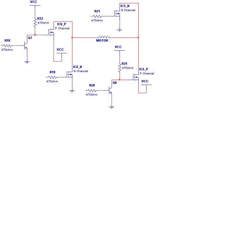
Ok, well I’ve done some futher work on the motor mount method for nelly and I’ve come up with this circuit:

This isn’t a final circuit at all, just a testing one. I still have some issues with the speed controll and things….


First tests haven’t been exceptionaly good. Nothing blew up but the turbo is not giving the full propo speed… Also, fwd seems to have issues.. I have some ideas and I believe I might know what’s wrong so I’ll keep on plugging!
ph2t.
Edited by – ph2t on 11 May 2004 02:22:29
-
May 13, 2004 at 8:18 pm #51423
Ph2t you have a pm
-
June 15, 2004 at 8:02 pm #52440
Well, lets just say that I’m still going on with this. I’ve started trialing some new MOSFETS that are even better performing ones that the current setup. nelly 1.1 has 30% more power than my original nelly 1.0.
I’ve also just come across some even newer MOSFETS that (if workable) have the ability for nelly to push even more hardcore energy! yeah baby!
So far nelly’s 1.0 and 1.1 are going well and never heating up. My mini-z madforce with a plasma dash motor and 14T pinion STILL pops wheelies! You gotta love it.
Here’s some info that shows you how Woah Nelly (theoretically) compares to the age old method of FET stacking.


Now if only my mr01 and madforce weren’t outta commision I’d get some video happening. I busted my madforce’s rear shock – pillow ball mount. Don’t have a spare:evil:! This is what happens when you launch the madforce from the roofs of mates’ cars.:p
ph2t.
-
June 15, 2004 at 8:45 pm #52450
…ok baby…lets sort this out…what do you need?
-
June 15, 2004 at 9:24 pm #52452
I have noticed on the Nelly 2 you have taken ‘YOKO’ out of the equation. Does this mean the Beatles are getting back together now?
-
June 15, 2004 at 9:27 pm #52453
…i actually have a girl in one of my classes whose name is Yoko Ono…kinda weird…
…Ph2T send me a list of parts needed mate…
-
June 16, 2004 at 12:31 am #52467
Likewise, please keep me up withthe required parts as my wholesaler may have them in more manageable quantities.
It’s either tat or we sit down with Bithed 😉
A.
--
Site Owner Guy. -
June 24, 2004 at 1:14 am #52748
the diagram:
http://www.geocities.com/mastermind_sound_solutions/NFUD.htmlFrom top to bottom, the first and third FETs are N channel IRL3705 FETs, the second and fourth FETs are IRF4905 P channel FETs.
is this how you would get these two fets working on a mini z?solder it exactly the same way?
or it only works on iweaver? -
June 24, 2004 at 1:25 am #52749
i waver and kyosho use the same sorta fets so if that works on a z it will work on an i waver and vice versa. i’m no techo but that pic looks about right:8ball:
-
June 24, 2004 at 2:03 am #52751
so you mean to say it would wire or solder the same???/ and is ok for miniz?
-
June 24, 2004 at 2:13 am #52752
so it would connect the same way as in the diagram and wont wreck the miniz??
-
June 24, 2004 at 2:45 am #52755
don’t waste your time with that mod…….
If you’re going to the trouble of doing that, use the fets I mentioned at the begining of this thread, they offer way better performance.ph2t.
-
June 24, 2004 at 2:53 am #52757
i heard about these in may 22nd’s issue of newscientist, i thought they could be of interest… they are called finFETs are they of any use in this application? hope this info helps:
http://www.diegm.uniud.it/ulis2003/presentazioni/117_Burenkov.pdf
-
June 24, 2004 at 2:58 am #52758
i wouldnt be wasting my time if i didnt need to
but because my friend bought the rong ones of ebay for 25$ im stuck with these nowso just wandering how to use it would it be exactly the same as the link http://www.geocities.com/mastermind_sound_solutions/NFUD.html
to connect to a mini z?
-
June 24, 2004 at 3:02 am #52760
Z, interesting man, thanks for the info. The main app for the finfets is size. The mass production of these fets would end up in top end IC/Processor design, not power mosfets. But hey! I dig brutha, I dig…..
hnm738, lemme check out the spec on the fets you have and I’ll let you know tomorrow. Gotta crash now, got a 7:45am meeting to attend tomorrow…. arghhhh, bloody management meetings…..
ph2t.
-
June 24, 2004 at 3:10 am #52761
thats great
thanks ph2t
-
June 24, 2004 at 3:19 am #52762
thought all the tech savvy ausmicrons (resident of planet ausmicro) might appreciate this new type of fet.
the article was about getting around the problems of moores law, you know that theory of miniturization of technology increasing exponentialy.
i would have thought someones made bigger ones than nanometer scale to use in other things, like making z’s that much better! oh well
-
June 24, 2004 at 3:26 am #52763
off topic:p but z, or anyone did you catch the latest issue with the article on miniature combustion engines? dead set, some smarty pants made a w@nkel rotary engine measuring 20mm across!!! puts out 10 watts:8ball:
-
June 24, 2004 at 4:03 am #52765
awesome. i want one for my rx-7 bcg!!!
-
June 24, 2004 at 10:30 am #52767Quote:off topic:p but z, or anyone did you catch the latest issue with the article on miniature combustion engines? dead set, some smarty pants made a w@nkel rotary engine measuring 20mm across!!! puts out 10 watts:8ball:
Oh my God!! Oh my God!!
I need a copy of that article – and then I need that motor.
-
June 24, 2004 at 12:11 pm #52768
here u go heres a link to it :
http://www.me.berkeley.edu/mrcl/mini.html -
June 24, 2004 at 12:13 pm #52769
if u think that cool click the micro engine link.. that thing is truely micro
-
June 24, 2004 at 3:06 pm #52773
Dude thats nothing, some research place built a rotary with a 1mm rotor.
-
June 24, 2004 at 3:08 pm #52774
-
June 24, 2004 at 6:41 pm #52780
jamie, 2 cm would be perfect for a bcg. 1mm would be rediculous but its an amazing acheivement all the same!
-
June 24, 2004 at 8:41 pm #52787
Dyno charts and all!!!
-
June 29, 2004 at 3:00 am #52951
Ok, lets bring this bugger back on to topic.:evil:
I’ve now changed the layout of the PCB to move the motor mount to one edge. This helps with the alignment when nelly is installed. I’ve made just a few (physical) improvements on the original design in terms of layout and total size.
Here’s some updated shots of the latest version of nelly.


As you can see, setup is pretty simple. Solder the 2 power wires to the +/- battery terminals. Solder the 4 (rainbow) wires to the RX pcb, two soldered per mosfet package. Then you just need to terminate the motor cables into the orange wire block and you’re good to go!
cheers,
ph2t.
Edited by – ph2t on 28 June 2004 23:09:26
-
July 1, 2004 at 6:49 pm #53066
Dude wheres my nelly!! I’m sick of my Xmod……after 1 minute of driving the FETs heat up and get very laggy. There is bugger all punch coming from this car. Can’t wait for some AWD DORI DORI….
Soon its gonna have:
AWD or Front wheel drive (yeehaa!!)
Suspension and tie rod kit
Aluminium tube D/S
Lithium-Ion cells (7.4v total)
Stage 2 heatsink
11t pinion
Dry BB’s
JK F1
Whoa nelly 1.1 turboShould be a potent machine, it *should* drift on tarmac with this sort of grunt….but man the drivetrain will suffer, I’m gonna put heatshrink on the outdrive cups, stops them flexing and breaking, but it probably wont quite cut it. Alloy ones are quite pricey……:sad:
-
July 1, 2004 at 9:42 pm #53076
Geez matt, that looks pretty flash…
-
July 3, 2004 at 11:31 pm #53122
Forget it.
Edited by – Charlie Brown on 04 July 2004 00:43:30
-
July 3, 2004 at 11:41 pm #53123
how the hell is this meant to make things easier?
the source pins on all fets are wired to the wrong voltage rail. the pchan fets goto Vcc, the nchan fets goto GND.
ph2t.
-
July 4, 2004 at 2:49 am #53130Quote:how the hell is this meant to make things easier?
the source pins on all fets are wired to the wrong voltage rail. the pchan fets goto Vcc, the nchan fets goto GND.
ph2t.
Umm..:dead:What’s vcc/GND?
I based the linking of the FETs on neurokinetik’s way of connecting the FETs, the gate signal pads connect to the gates of the corresponding P or N channel FET, the source pin is connected to the corresponding battery terminal (is that correct, or does that apply just to neuro’s way and not this way? :dead:), and the drain is connected to the appropriate motor lead….
But vcc? Does GND= Ground? AHHH…TOO…CONFUSING…I…NEED…AIR!!!
Edit: and by “easier” I mean “Easier to read”…..lol :question:
Edited by – Charlie Brown on 03 July 2004 22:51:09
-
July 4, 2004 at 2:55 am #53131
echo…….
your source pins are connected to the wrong terminals. review the various diagrams you have used for reference and you will see your mistake.
Charlie, I’m not going to answer your questions just because you are too lazy to search and find out for yourself. You did this to Jshwaa over at tinyrc, don’t expect to get away with it here. Grow up.
Btw, why do this diagram? Of what use is it to you?
-
July 4, 2004 at 3:36 am #53134Quote:echo…….
your source pins are connected to the wrong terminals. review the various diagrams you have used for reference and you will see your mistake.
Charlie, I’m not going to answer your questions just because you are too lazy to search and find out for yourself. You did this to Jshwaa over at tinyrc, don’t expect to get away with it here. Grow up.
Btw, why do this diagram? Of what use is it to you?
Ok, if by “wrong terminals” you mean I should switch the terminals for the source pins, then I got it. I did a search for “GND”, I know it means ground, but vcc….look ph2t, I don’t take an electronics class, and I ask q’s to gain information. So, what is VCC? I did a search on that dictionary site…I’m still learning hardcore electronic stuff.
The diagram I was making was basically taking the FETs you used, but linking and connecting them the way Neurokinetik at TRC connected his FETs….
So, in the diagram I made, what I infer is that I have to switch the P channel and N channel source connections…correct?
-
July 4, 2004 at 3:43 am #53136
i just don’t know where to start.
i can’t believe that someone who doesn’t know what Vcc and GND means has the ordasity to think that he can magically find an incredible breakthrough in the way electricity flows. this is not astrology, there are no mystic interpretations, there is absolutely nothing to be gained by arsing about with the wiring. you can wrap the wires around the bloody car but they all have to match up the way ph2t explained it.
you are not going to make any electronic breakthroughs with your current attitude. you cannot even begin to redesign the h bridge without understanding basic (common fer us bruces) electrical knowledge. i mean… i ….agh….. i’m choking on my rage over here!
even the dumbest ausmicro members know what i mean. please, learn to:a) comprehend information
b) listen to people who are educated in such matters
c) walk before you can run
d) stop annoying the crappin’ bajeezus out of people for the afformentioned reasons (or any other for that matter):8ball: -
July 4, 2004 at 3:47 am #53138
(man o man!!!!:dead:)
lesson 1.
red wire +
black wire not +:8ball:
-
July 4, 2004 at 3:50 am #53139
Charlie, using dictionary.com will not help you with electronics 101. Use this site instead: http://www.iserv.net/~alexx/glossary.htm
and piss off while your at it.
ph2t.
-
July 4, 2004 at 4:38 am #53142
You guys should know better than to pick on an 11 y.o. extremely mentally challenged american child!!
Remember:
Everytime you masturbate, god kills son_gokou/charlie brown (pinched off bp)
So guys….jerk away!!
-
July 4, 2004 at 4:45 am #53143Quote:You guys should know better than to pick on an 11 y.o. extremely mentally challenged american child!!
Remember:
Everytime you masturbate, god kills son_gokou/charlie brown (pinched off bp)
So guys….jerk away!!
Wow, you sure get pissed off very easily. 😯
Just a few questions as to how it works to get a better understanding….And you insult me and the country I’m living in. What’s wrong with this picture? :question:
-
July 4, 2004 at 4:58 am #53144
Take a hint…….
-
July 4, 2004 at 12:56 pm #53151
Yeah I got the hint…what I did was stupid.
After some more analyzing, I understand ph2t’s diagram.
I’ll admit I was being a twat back there, trying to create my own way of the h-bridge when I don’t know the h-bridge basics.
Let’s just forget all this sh1t, and continue what was interrupted before I started posting….
Ph2t, are you selling these babies?
-
July 4, 2004 at 1:19 pm #53152
this is (again!!) another question that can be answered by READING AND COMPREHENDING WRITTEN….. oh forget it. you’ll never learn:8ball:
-
July 4, 2004 at 5:44 pm #53160
oi. you guys seem to know alot about electronic stuff. i know some stuff but not that much. was driving my car and all of a sudden the reverse stopped working. tried heaps of stuff to try and fix it but wouldn’t have a clue whats rong. please help cause it gets really irritating when you have to keep getting up and turning your car around cause you’ve hit somthing. please help
-
July 4, 2004 at 5:57 pm #53161
sounds like you’ve blown one of the fet pairs…. This would explain why one direction works and not the other. what were you running? an xspeed? what chassis? mr01? madforce? etc..etc….
in future please start a new thread and not hijack someone else’s….
cheers,
ph2t.
-
July 4, 2004 at 6:31 pm #53162
ph2t, thought I’d try to help you with finding some FETS with a high current handling capability, and a low RDS on value at 4.5V.
http://www.vishay.com/mosfets/r-ds-on-lteq-10-milliohms/i-d-max-gteq-20-a/
Some examples:
SUM110P06-07L- 110A, 0.0088 ohms RDS on value at 4.5V, P channel
SUM110P04-04L- 110A, 0.0062 ohms RDS on value at 4.5V, P channel
SUM110N02-03P- 110A, 0.0052 ohms RDS on value at 4.5V, N channel
SUM110N02-03- 110A, 0.0026 ohms RDS on value at 4.5V, N channel
SUM110N03-03P- 110A, 0.0026 ohms RDS on value at 4.5V, N channel -
July 4, 2004 at 7:31 pm #53164
i’m runnin a standard iwaver but with these crazy batteries i got.; when i first got the car, i wacked some grandcell rechargeables in it(never use them they the worst things ever) and it went pretty slow. it then slowed down considerably and i thought that was a bit odd. picked it up and there was smoke comin out the bottom of it.then when i used it from then on, forward was way slower than reverse, so i switched the motor terminals and changed the switch on my controller so when i pulled the trigger the car went forwards instead of backwards. then put these new batteries in it today and it went for a bit, then i hit something and it just stopped. so switched it all back to normal(all the conections etc) and was hoonin it forward but now reverse doen’t work
-
July 4, 2004 at 8:21 pm #53166Quote:i’m runnin a standard iwaver but with these crazy batteries i got.; when i first got the car, i wacked some grandcell rechargeables in it(never use them they the worst things ever) and it went pretty slow. it then slowed down considerably and i thought that was a bit odd. picked it up and there was smoke comin out the bottom of it.then when i used it from then on, forward was way slower than reverse, so i switched the motor terminals and changed the switch on my controller so when i pulled the trigger the car went forwards instead of backwards. then put these new batteries in it today and it went for a bit, then i hit something and it just stopped. so switched it all back to normal(all the conections etc) and was hoonin it forward but now reverse doen’t work
yeah dude, you’ve blown a mosfet….. you need to replace it to get it working all ok again….
-
July 4, 2004 at 8:30 pm #53167Quote:ph2t, thought I’d try to help you with finding some FETS with a high current handling capability, and a low RDS on value at 4.5V.
http://www.vishay.com/mosfets/r-ds-on-lteq-10-milliohms/i-d-max-gteq-20-a/
Some examples:
SUM110P06-07L- 110A, 0.0088 ohms RDS on value at 4.5V, P channel
SUM110P04-04L- 110A, 0.0062 ohms RDS on value at 4.5V, P channel
SUM110N02-03P- 110A, 0.0052 ohms RDS on value at 4.5V, N channel
SUM110N02-03- 110A, 0.0026 ohms RDS on value at 4.5V, N channel
SUM110N03-03P- 110A, 0.0026 ohms RDS on value at 4.5V, N channellol, nice work. don’t see why you couldn’t use those. Their pkg’s are big though. I like to be as small as possible. The fets I’m using have stats better than those but thanks….lol….
-
July 4, 2004 at 9:02 pm #53169
how the hell do u replace a mosfet. its crappy cause i live in byron bay on the coast and not many people here have z’s. the fella at my hobby shop is pretty smart he might be able to fix it. yay
-
July 5, 2004 at 4:25 pm #53190Quote:how the hell do u replace a mosfet. its crappy cause i live in byron bay on the coast and not many people here have z’s. the fella at my hobby shop is pretty smart he might be able to fix it. yay
You have to desolder them from the board…Using a soldering iron, heat the legs…you might wanna pick up a desoldering braid from the store…Place it carefully on the mosfet leg/s, heat it with the iron (making sure the iron doesn’t touch the chassis….lol), and the braid will absorb the solder off the legs, but do it carefully or you could melt the copper pads on which the legs are soldered to.
And those people in your area who don’t have Z’s (including Iwavers) don’t know what their missing…lol
-
July 5, 2004 at 4:26 pm #53191Quote:Quote:ph2t, thought I’d try to help you with finding some FETS with a high current handling capability, and a low RDS on value at 4.5V.
http://www.vishay.com/mosfets/r-ds-on-lteq-10-milliohms/i-d-max-gteq-20-a/
Some examples:
SUM110P06-07L- 110A, 0.0088 ohms RDS on value at 4.5V, P channel
SUM110P04-04L- 110A, 0.0062 ohms RDS on value at 4.5V, P channel
SUM110N02-03P- 110A, 0.0052 ohms RDS on value at 4.5V, N channel
SUM110N02-03- 110A, 0.0026 ohms RDS on value at 4.5V, N channel
SUM110N03-03P- 110A, 0.0026 ohms RDS on value at 4.5V, N channellol, nice work. don’t see why you couldn’t use those. Their pkg’s are big though. I like to be as small as possible. The fets I’m using have stats better than those but thanks….lol….
lol, well since they’re bigger they could probably handle more heat/power or something…haha
-
July 5, 2004 at 7:19 pm #53192
But theres no point dude….
-
July 5, 2004 at 8:46 pm #53197
Hey Jamie, check your mailbox dude….
and here’s the solder points, colour coded to the nelly I sent you….

cheers,
ph2t.
-
July 6, 2004 at 3:14 pm #53214
After some play-by-play updates by Jamie I can now happiliy confirm that nelly works well on the XMOD.
thumbs up!
ph2t.
-
July 6, 2004 at 4:35 pm #53218
Charlie you douche bag, copper melts at 1043 degrees centigrade, no soldering iron will melt it…..
Ph2t thanks alot for your help, it was the easiest FET mod i’ve ever done!!
-
July 6, 2004 at 5:18 pm #53221
your Xmod performing now Jamie? May have to procure the services of a whoa nelly ph2t…
-
July 6, 2004 at 5:23 pm #53222
Get one mate, they are sick!! The use one of my motors and bam!
-
July 7, 2004 at 4:40 pm #53250
I’ve changed the orientation of the motor terminal block now to improve clearance for those really low shells.

Here’s a nelly installed on Tim’s mr-01.

I’ve settled into the method of feeding the cables out the front. This allows those people using the centre damper shock avoid any conflict of space with nelly. All I did was gouge out a bit of the plastic on the PCB cover and this allowed the cables to pass through no sweats.

Now to get off my butt and get some proper install doco happening…..
ph2t.
-
July 7, 2004 at 7:27 pm #53257
If this beast becomes installable without soldering, I’m gunna want one of ’em. But it’s gotta be V1.X > Timmy’s V1.1
😀BTW, if you tug at it, will it rip from the solder joints ?
-
July 7, 2004 at 9:26 pm #53264
no turbo is a solder free install. you’ll need to solder wires to the battery terminals at least. and if you tug at any components or module you’ll rip it out!! why would you wanna tug ya turbo when you can………….:blush::8ball:
-
July 7, 2004 at 9:47 pm #53267
Sif ph2t use a picture of my car to advertise
your whoa nelly!:evil: Now everyone seen it naked:blush::blush:
j/k
-
July 7, 2004 at 10:10 pm #53268
What, you did what i and everyone else told you to do…
Well i never:approve: -
July 7, 2004 at 11:23 pm #53270
kevsta, if you tug at the turbo, nothing will happen. If you pull at it really hard, you could *possibly* do damage. Please note that the turbo is anchored VERY well, your idiot dial would need to be turned to 11 to break it off……
Tim, I brought your Z back from the dead dude, lol, and you know it. Let’s see here… hmm, stripped screw holes, busted wires, bridged solder tracks, exposed wires and one butt ugly mutant half concieved fet stack that I put to rest….lol…..
Pete, dude you’re making as much sense as always……:approve:
ph2t.
-
July 8, 2004 at 2:44 am #53273Quote:Quote:how the hell do u replace a mosfet. its crappy cause i live in byron bay on the coast and not many people here have z’s. the fella at my hobby shop is pretty smart he might be able to fix it. yay
You have to desolder them from the board…Using a soldering iron, heat the legs…you might wanna pick up a desoldering braid from the store…Place it carefully on the mosfet leg/s, heat it with the iron (making sure the iron doesn’t touch the chassis….lol), and the braid will absorb the solder off the legs, but do it carefully or you could melt the copper pads on which the legs are soldered to.
And those people in your area who don’t have Z’s (including Iwavers) don’t know what their missing…lol
Actaully the easiet way to remove the stock fets is to add a shitload of solder to the pins and just keep heating each side continuously. Then you will be able to push the stock fets of the board with the soldering iron. Then clean it up with desolder braid.
Watch this guide.
http://www.insflug.org/shots/fetremove.asf
That shows best how to remove FETS. -
July 8, 2004 at 12:49 pm #53279
ph2t, this is all just genius…AWESOME….but could you show us some pics on attaching the motor to the motor terminals on nelly? Thanks man!
Edited by – Charlie Brown on 08 July 2004 08:49:30
-
July 8, 2004 at 1:29 pm #53283Quote:Actaully the easiet way to remove the stock fets is to add a shitload of solder to the pins and just keep heating each side continuously. Then you will be able to push the stock fets of the board with the soldering iron. Then clean it up with desolder braid.
Watch this guide.
http://www.insflug.org/shots/fetremove.asf
That shows best how to remove FETS.Actually thats a BAD idea, too much heat can destroy the adhesive between the fibreglass PCB and the tracks.
The EASIEST METHOD i have found is to cut all 8 legs off the ic’s (who wants 3004’s anyway???)
and clean and tin each pad…..if any of the pads lift when you do this you are retarded. -
July 8, 2004 at 5:04 pm #53292Quote:ph2t, this is all just genius…AWESOME….but could you show us some pics on attaching the motor to the motor terminals on nelly? Thanks man!
Edited by – Charlie Brown on 08 July 2004 08:49:30
Dude it ain’t that hard. Just get the two motor wires and push them into the orange terminal block. Then screw in the terminal block screws to hold the wires in place and your done.
-
July 8, 2004 at 5:38 pm #53295
yeh i agree with jamie… aslong as ur not stupid removing and replacing fetts isnt hard.. that method of fett removal is good..and soldering them in is easy (i like to glue them down witha non conductive glue first (only abit … not on any of the pads just the base of the fet
-
July 8, 2004 at 8:15 pm #53303Quote:Quote:Actaully the easiet way to remove the stock fets is to add a shitload of solder to the pins and just keep heating each side continuously. Then you will be able to push the stock fets of the board with the soldering iron. Then clean it up with desolder braid.
Watch this guide.
http://www.insflug.org/shots/fetremove.asf
That shows best how to remove FETS.Actually thats a BAD idea, too much heat can destroy the adhesive between the fibreglass PCB and the tracks.
The EASIEST METHOD i have found is to cut all 8 legs off the ic’s (who wants 3004’s anyway???)
and clean and tin each pad…..if any of the pads lift when you do this you are retarded.I guess everyone has there own way :smiley2:
-
July 9, 2004 at 2:55 am #53317
ph2t will back me up on that!!
-
July 9, 2004 at 3:42 am #53324
lol, yeah chris, the best way is to just cut them off mate. the less heat exposed to the copper pads at any time, the better…
you did say easiest though, and it’s appears quicker and easier than sitting there with a stanely knife trying to the slice your finger off…….:shock:
:approve:
I hate writing doco, reminds me too much of work……
ph2t.
-
July 9, 2004 at 3:24 pm #53334
It becomes quite hard when the copper pads lift…..the first time that happened i though i needed a new pcb, but i removed the “black box” and traced the tracks back and double checked th with a DMM, then added a wire link to the FET stack.
-
July 9, 2004 at 3:24 pm #53335
Im not much of a fan of stanley knifes 😀 Ive had to many close calls with them :shy:
-
July 9, 2004 at 3:32 pm #53336Quote:It becomes quite hard when the copper pads lift…..the first time that happened i though i needed a new pcb, but i removed the “black box” and traced the tracks back and double checked th with a DMM, then added a wire link to the FET stack.
How the hell do you remove the black box!
-
July 9, 2004 at 3:40 pm #53339
desolder it……..but make sure you don’t force it, as the plates can come right out of it….(don’t even ask)
-
July 10, 2004 at 2:42 am #53359
I think ill leave it where it was…
Mines in pretty bad shape atm, alot of plastic has been taken from it lol 😀 -
July 12, 2004 at 1:32 pm #53419
lol dude, be careful, i dunno where you would find another one of those things….
-
July 13, 2004 at 12:37 am #53443
Yeah i was thinking that too. so i want to add some plastic to it now 😛 just to be safe. I’ve heard its a RF filter of some sort :question:
-
July 13, 2004 at 3:52 pm #53458
add plastic?? why? just don’t touch it!
-
July 13, 2004 at 10:33 pm #53476
If it aint broke – dont **** it up … err I ment dont fix it 🙂
It took me 6 RC vehicles to learn that one,
(Though I dont count improvng as the same thing as fixing) -
July 13, 2004 at 11:42 pm #53477
hey kitsune, welcome to the boards man!
ph2t.
-
July 13, 2004 at 11:45 pm #53478
yeh if u dont know wat it is (so u cant replace it) dont fiddle… its fine to rip out fets if u know wat they are.. but somthign that you recognise as a “black box” i wouldnt touch
-
July 15, 2004 at 12:16 am #53511
The thing is i thing i am getting problems from it. But we will see once a nelly is installed and the car is going again finally. 🙂
-
July 16, 2004 at 4:40 pm #53599
If it isn’t broken, modd the fuck out of it till it is 👿
-
July 18, 2004 at 4:58 pm #53675
Been doing a little thinking while I’m trying to source some of ph2t’s uber fets 🙂
Unfortunately Its left me with a few questions …ph2t – is there a reason you havn’t stacked the fets on Nelly? I know it would put the cost up, but wouldn’t you further reduce the resistance and increase the max current? (ok weight and cost go up, but would it work and would it bring any noticeable performance differance?)
Could someone correct me if I’m wrong but doesnt the mini-z/iwaver regulate speed by pulsing power to the motor … more pulses = more frequently the motor is reciving power = car goes faster, has anyone experimented with putting a cap (larger than the 104 or 103’s for reducing interference) to smooth out power going to the motor? (to large a Cap will make speed changes sluggish I think but the right size might help. Any attempts / info.
Also on the topic of caps are any of you putting caps across the battries to improve the car’s acceleration? (asside from the one on Nelly 2) used to do it on race tins, and I figure it should work here too.
Thanks
ph2t – seeing as you’ve managed to source these awesome fets would you be willing to resell/spill the beans on where you’re getting them?
Edited by – kitsune on 18 July 2004 13:15:43
-
July 18, 2004 at 5:04 pm #53677
nah speed in controlled by just increasing power to the motor (propo)… servos are controlled much more different . and lets not go ther
-
July 18, 2004 at 5:29 pm #53678
the caps are to stop the generator affect… lorenz law as well as simple induction (oppose change in flux blah blah blah) bassicaly it gennerates a reverse current the caps just block that and when the current forward chanegs they discarge
-
July 18, 2004 at 5:54 pm #53681
Lorenz’s Law of Mechanical Repair: After your hands become coated with grease, your nose will begin to itch.
(Or do you mean Lorenz force Law?) 🙂
If the power to the motor is pulsed a larger cap across the wires to the motor would smooth out the pawer and cause it to run smoother – less arcing from the brushes (which causes interference to the radio signals controlling the car) shortens their life span, and causes pitting which increases their electrical resistance when it come to pushing power to the com – all bad things. plus the car might run faster because during the non pulse moments the motor isn’t acting as a generator.
if as you say its voltage regulated then all the caps gonna do is slow down the responsiveness of the motor (kinda like having a spring on your accellerator pedal, takes longer to react to accelleration + decelleration)
-
July 18, 2004 at 6:04 pm #53682
hmm i might be wrong.. oh well.. but im prety sure thatteh caps are to stop revers curret that is generated but the spinning of the motor..
-
July 18, 2004 at 6:29 pm #53684
I had the same idea of stacking the FETS on the whoa nelly. If one whoa nelly FETS is equilavent to 12×2 7389 and if i stack it 6×2 of whoa nelly FETS that equals to 72 7389!!!!!!:shock::shock:
My dream is now get heaps of whoa nelly and stack them and called them the ‘unfrieable’ and sell them and beat ph2t :smiley2::smiley2:
-
July 18, 2004 at 7:10 pm #53689
The only problem I can see there is diminishing returns.
After all making aperfect turbo won’t change the resistance in the motor, wires, battery contacts and the batteries themselves, now will it allow the battery to push more than it’s capable of, to get an idea of the maximum speed a car is capable of with the existing motor + gearing etc hook up the batteries directly to the motor, (If anyone does this I’d love to know the results) and run it on a dyno + compare to when the speed’s being regulated by a turbo or the onboard fets. (ok dyno results arn’t entirely accurate but they give a feel for the situation.
I’d relly be interested in the top dyno speeds of a) the same car with standard fets,
b) the same car with Nelly,
c) the same car with a stacked Nelly,
d) the same car with the batteries tied in directly to the motor,even if we can’t get figures on a stacked nelly the other figures would be interesting to see how much of the car’s potential you can reach with Nelly.
You could even use a formula such as
(rating)=(nelly speed boost)/(Potential speed boost)
(Rating)=(b-a)/(d-a)(you could sub other turbos etc to get rating for other options)
(the following is using imaginary figures)
eg. if a car with stock fets goes 15kph (a)
and It’ll go 35kph with a nelly (b)
and with the batteries hooked directly to the motor goes 45kph (d) its rating would be …rating = (b-a)/(d-a)
rating = (35-15)/(45-15)
rating = 20/30
rating = .6666 (or 2/3)so on that car nelly would provide 66% of the potential speed increase that the car is capable with those parts in it. (roughly ther’s some minor details that I’m leaving out such as power drain from the controller etc.
Thoughts? Results?
-
July 18, 2004 at 11:42 pm #53693Quote:Been doing a little thinking while I’m trying to source some of ph2t’s uber fets 🙂
Unfortunately Its left me with a few questions …ph2t – is there a reason you havn’t stacked the fets on Nelly? I know it would put the cost up, but wouldn’t you further reduce the resistance and increase the max current? (ok weight and cost go up, but would it work and would it bring any noticeable performance differance?)
No reason why I haven’t stacked them. I want to get the best possible fets first. It’s an intrinsic thing…:smiley2: There would be a performance difference, there always is. How much? Only real world tests would possibly show.
Quote:Could someone correct me if I’m wrong but doesnt the mini-z/iwaver regulate speed by pulsing power to the motor … more pulses = more frequently the motor is reciving power = car goes faster, has anyone experimented with putting a cap (larger than the 104 or 103’s for reducing interference) to smooth out power going to the motor? (to large a Cap will make speed changes sluggish I think but the right size might help. Any attempts / info.The speed control used is nothing different from traditional methods. PWM = Pulse Width Modulation. It’s more about the width of the pulse and for how long within one cycle is it on for. This is also known as duty cylce. 10% duty cyle means the pulse is on for 10% of the time in one cylce. Once cylce could easily be 1/1000th of a second long. 90% duty means the pulse is high almost all of the time. Obviously the greater the duty cycle, the greater the average power delivered to the motor. Hence, speed control.
Putting a capacitor across the output terminals will have a negative effect. This is because the cap will sink current when the motor should be. Since this is a cylce, the cap will always be reset and therefore always sinking current to fill it up again.
Putting a cap across the battery though should improve acceleration BUT at this scale people have stated that the effects are minimal. Personally I’m yet to try this, I believe with the right capacitor it could work. You would want a capacitor that had a really low ESR value. (Equivalent Series Resistance, avail on cap datasheets…) A low ESR is like a set of punchy ni-cd’s. The low ESR allows the capacitor to discharge a high current. This is the goal in increasing performance though using a capacitor across the battery terminals….
Quote:Thanksph2t – seeing as you’ve managed to source these awesome fets would you be willing to resell/spill the beans on where you’re getting them?
http://www.digikey.com – Shipping is a bitch, but beggars can’t be choosers(spelling?)…..
cheers,
ph2t.
-
July 18, 2004 at 11:46 pm #53694Quote:hmm i might be wrong.. oh well.. but im prety sure thatteh caps are to stop revers curret that is generated but the spinning of the motor..
the caps quench high frequency noise generated by the motor.
You’re thinking diodes man. A diode is put across a coil to sink the current generated in the opposite direction when a magnetic field colapses, ie: voltage is removed.
ph2t.
-
July 19, 2004 at 1:28 am #53699
ph2t – thanks for the detailed response.
are you going to be doing an order with digikey in the near future? if so would you be interested in adding some bits on for me and I’ll chip in towards shipping?
How goes the search for even better fets?
If the newer mosfets are useable could you let me in on their part numbers, Digikey out of stock of the IRF7425 – and looks like they will be for over a month. -
July 19, 2004 at 9:05 pm #53739
I have tried putting the capacitor accross the motor terminals. It was a 6v 3300uF cap, to tell you the truth it wasnt really much different, maybe a tiny tiny bit more punchy down the bottom of the rpm range.
It isnt really worth it unless you find caps with low internal resistance so they can actaully give you the power you need straight away in one big heap. -
July 19, 2004 at 9:50 pm #53740
my point exactly.:approve:
the only caps that have mega-ultra-superhappy low ESR are tantulum. Do some searching for KEMET & EPCOS, they make some great low ESR caps.
You could prolly get them at digikey, hmmmm, wondering……..
The EPCOS ones come out of the Siemens plant in Bayswater, around the corner from where I used to work..!
😀
ph2t.
-
July 19, 2004 at 9:52 pm #53741
WARNING reverse polarised tantalum caps pop bigger than other caps.And can do damage
-
July 20, 2004 at 11:48 pm #53801
lol i watched 4 of them blow up last wednesday, was pretty funny. At tafe my mate had finished his project and hadnt put the caps in the right way, plugged her in and we just heard a pop and lots of smoke 😀
-
August 8, 2004 at 4:35 am #54265
hey kitsune, here’s how I solder the IRF6609 mosfets in nelly 1.2:

Tricky buggers, the DirectFET package the IRF6609’s use sinks heat so well that it’s very easy to re-melt previous solder joins whilst soldering the wire on, damn!!!!
Nelly Deluxe
She’s mah new baby. Not much really. It’s a nelly 1.2 with a 4.8V regulator setup. This allows me to run up to 20V (mosfet limit) into a chassis BUT still have a regulated 4.8V output to goto the rest of the receiver PCB. This way the RX and steering circuits are NOT affected by the increase in supply voltage, they will always be set at the safe level of 4.8V. The drive train part of nelly deluxe is wired straight into the high voltage source allowing it to take full advantage of this extra voltage.


more to come……
ph2t.
-
August 8, 2004 at 4:35 am #54623
hey kitsune, here’s how I solder the IRF6609 mosfets in nelly 1.2:
Tricky buggers, the DirectFET package the IRF6609’s use sinks heat so well that it’s very easy to re-melt previous solder joins whilst soldering the wire on, damn!!!!
Nelly Deluxe
She’s mah new baby. Not much really. It’s a nelly 1.2 with a 4.8V regulator setup. This allows me to run up to 20V (mosfet limit) into a chassis BUT still have a regulated 4.8V output to goto the rest of the receiver PCB. This way the RX and steering circuits are NOT affected by the increase in supply voltage, they will always be set at the safe level of 4.8V. The drive train part of nelly deluxe is wired straight into the high voltage source allowing it to take full advantage of this extra voltage.
more to come……
ph2t.
-
August 8, 2004 at 5:58 am #54266
Oh DAMN, now I’m definitely gonna buy the Woah nelly deluxe… how much will that bitch cost ph2t? 😯
-
August 8, 2004 at 5:58 am #54624
Oh DAMN, now I’m definitely gonna buy the Woah nelly deluxe… how much will that bitch cost ph2t? 😯
-
August 8, 2004 at 2:24 pm #54268
not for sale….. purely an experimental version.
-
August 8, 2004 at 2:24 pm #54626
not for sale….. purely an experimental version.
-
August 8, 2004 at 2:37 pm #54269
Looks great, now get some video action going. 😀
-
August 8, 2004 at 2:37 pm #54627
Looks great, now get some video action going. 😀
-
August 8, 2004 at 3:35 pm #54270
I fried it! ARGGHHHHHHHHH! And I know why now as well. I’m an idiot, I should of picked up on it earlier.
Gotta change the design…..What a waste too! Those fets cost me $20SUD. shit shit shit shit shit!
:dead:
ph2t.
-
August 8, 2004 at 3:35 pm #54628
I fried it! ARGGHHHHHHHHH! And I know why now as well. I’m an idiot, I should of picked up on it earlier.
Gotta change the design…..What a waste too! Those fets cost me $20SUD. shit shit shit shit shit!
:dead:
ph2t.
-
August 9, 2004 at 1:56 pm #54283
and what was it??
-
August 9, 2004 at 1:56 pm #54641
and what was it??
-
August 9, 2004 at 2:29 pm #54285
With the 6609’s try resting them on a metal block to draw some of the heat away when soldering, it might make things easier.
good luck with the redesign – care to go into more detail of what went wrong?
-
August 9, 2004 at 2:29 pm #54643
With the 6609’s try resting them on a metal block to draw some of the heat away when soldering, it might make things easier.
good luck with the redesign – care to go into more detail of what went wrong?
-
August 9, 2004 at 2:30 pm #54286
The issue was the p-chan mosfets. Now that I have the regulator setup to maintain a Vcc of 4.8V to the RX circuit the output from the RX circuit into the mosfets will be 4.8V for the “on” state and still 0V for the “off” state.
For a pchan to turn on the voltage at the gate pin must be at a lower potential than Vcc. For the pchan to be off the gate pin voltage must be at the same potential as Vcc.
Can you see the issue? Vcc for the nelly h-bridge is now 7.2V. But the gate pin potential will only be as high as 4.8V (the output signal from the kyosho RX PCB). For a 4.8V potential on the gate pin the mosfet would normally be off. BUT now there is two Vcc’s. The RX Vcc of 4.8V and the nelly Vcc of 7.2V. The pchan mosfet should be off, but now it isnt. The gate pin is 2.4V LESS than Vcc, this means that BOTH P-CHAN mosfets in the nelly h-bridge are on!!! All i did was push fwd on the TX and that turn on one of the n-chan mosfets. This caused a short circuit and therefore blew the p-chan (and eventually the nchan) mosfets.
To solve the problem i need to bring the output from the RX for an “off” signal (talking pchan here) of 4.8V to 7.2V. This way the pchans stay off and will only turn on when they are meant to.
I’ve decided to use a pair of Maxim mosfet driver IC’s. Don’t have the part number on hand, I will post it and a full schematic over the next few days. The mosfet driver is like a buffer and it will be connected to the Vcc of 7.2V. This will translate a 4.8V signal to a 7.2V one but keep a 0V signal at 0V. This should get around this issue. It will also alow me to turn the mosfets on even better and improve the Rds(on) value of the mosfets to an even lower figure and increase efficiency buy about %60.
Make sense? prolly not, lol…..
ph2t.
-
August 9, 2004 at 2:30 pm #54644
The issue was the p-chan mosfets. Now that I have the regulator setup to maintain a Vcc of 4.8V to the RX circuit the output from the RX circuit into the mosfets will be 4.8V for the “on” state and still 0V for the “off” state.
For a pchan to turn on the voltage at the gate pin must be at a lower potential than Vcc. For the pchan to be off the gate pin voltage must be at the same potential as Vcc.
Can you see the issue? Vcc for the nelly h-bridge is now 7.2V. But the gate pin potential will only be as high as 4.8V (the output signal from the kyosho RX PCB). For a 4.8V potential on the gate pin the mosfet would normally be off. BUT now there is two Vcc’s. The RX Vcc of 4.8V and the nelly Vcc of 7.2V. The pchan mosfet should be off, but now it isnt. The gate pin is 2.4V LESS than Vcc, this means that BOTH P-CHAN mosfets in the nelly h-bridge are on!!! All i did was push fwd on the TX and that turn on one of the n-chan mosfets. This caused a short circuit and therefore blew the p-chan (and eventually the nchan) mosfets.
To solve the problem i need to bring the output from the RX for an “off” signal (talking pchan here) of 4.8V to 7.2V. This way the pchans stay off and will only turn on when they are meant to.
I’ve decided to use a pair of Maxim mosfet driver IC’s. Don’t have the part number on hand, I will post it and a full schematic over the next few days. The mosfet driver is like a buffer and it will be connected to the Vcc of 7.2V. This will translate a 4.8V signal to a 7.2V one but keep a 0V signal at 0V. This should get around this issue. It will also alow me to turn the mosfets on even better and improve the Rds(on) value of the mosfets to an even lower figure and increase efficiency buy about %60.
Make sense? prolly not, lol…..
ph2t.
-
August 9, 2004 at 3:30 pm #54290
Brilliant 🙂
The prob I had with my plans for a 4.8/7.2v system on the race tins had the same “both fets are always on” issue, unlike you however, I had no idea how to solve it and shelved it.
-
August 9, 2004 at 3:30 pm #54648
Brilliant 🙂
The prob I had with my plans for a 4.8/7.2v system on the race tins had the same “both fets are always on” issue, unlike you however, I had no idea how to solve it and shelved it.
-
August 9, 2004 at 4:36 pm #54294
you can use a standard pnp BJT like the BC558 in a “pull up” arangment but I had the mosfet drivers on hand.
Also the mosfet drivers are specifically desinged to source high currents for those first few microseconds when the gate pin is not in it’s “enhancement ” state.
ph2t.
-
August 9, 2004 at 4:36 pm #54652
you can use a standard pnp BJT like the BC558 in a “pull up” arangment but I had the mosfet drivers on hand.
Also the mosfet drivers are specifically desinged to source high currents for those first few microseconds when the gate pin is not in it’s “enhancement ” state.
ph2t.
-
August 9, 2004 at 7:44 pm #54310
here’s an example of what I mean about the bjt’s. Credit’s goto Jshwaa at the xmodsrc forum for the schematic.
cheers,
ph2t.
-
August 9, 2004 at 7:44 pm #54668
here’s an example of what I mean about the bjt’s. Credit’s goto Jshwaa at the xmodsrc forum for the schematic.
cheers,
ph2t.
-
August 24, 2004 at 3:55 am #55018
Ok, some quick news.
Development on Nelly 1.3 has started. :p
Nelly 1.3 will be approx 10% – 20% more efficient than Nelly 1.2
Nelly 1.3 will also be SMALLER than the Nelly 1.2 turbo.
more to come……:smiley2:
:approve:
ph2t.
-
August 24, 2004 at 9:44 am #55020Quote:Ok, some quick news.
Development on Nelly 1.3 has started. :p
Nelly 1.3 will be approx 10% – 20% more efficient than Nelly 1.2
Nelly 1.3 will also be SMALLER than the Nelly 1.2 turbo.
more to come……:smiley2:
:approve:
ph2t.
It will also probably COST more….:smiley2:
Anyway, have you found some new FETs for the turbo? If so, what are they?
Edited by – Charlie Brown on 24 August 2004 05:50:17
-
August 24, 2004 at 12:02 pm #55025Quote:Ok, some quick news.
Development on Nelly 1.3 has started. :p
Nelly 1.3 will be approx 10% – 20% more efficient than Nelly 1.2
Nelly 1.3 will also be SMALLER than the Nelly 1.2 turbo.
more to come……:smiley2:
:approve:
ph2t.
will it be mountable on the front then if it’s going to be smaller? Keen to get one eventually, but not if I cant run any shocks at all
-
August 24, 2004 at 12:59 pm #55030
All nelly’s are mountable at the front dude. See the installation doco. If’ you’re reffering to the work done on Talldudes iWaver, yes that was one of my firts mounting jobs which did conflict with the rear damper. But not now mate.
Just look at some pics of betty’s, tim’s or even my own Z. they all are mounted without infringing on the roll shock / rear damper setup.
cheers,
ph2t.
-
August 24, 2004 at 2:56 pm #55032
 :8ball:
 -
August 24, 2004 at 3:42 pm #55033
thanks betty, I hope this helps dave…..
ph2t.
-
August 24, 2004 at 6:47 pm #55035Quote:It will also probably COST more….:smiley2:
Anyway, have you found some new FETs for the turbo? If so, what are they?
Edited by – Charlie Brown on 24 August 2004 05:50:17
cost more huh? ok then charlie, well for you now it will cost more…
I’m not releasing what fets I’m using till I make sure it all works….. so there! hah!
ph2t.
Edited by – ph2t on 24 August 2004 15:24:14
-
August 24, 2004 at 7:28 pm #55038
Hmmm I’ve gotta try 😀
It will also probably COST less….:smiley2:infact ph2t will probably just give me one …
nope?
Ahhh well it if got charlie’s price jacked up I figured it was worth a try.
😀 -
August 25, 2004 at 1:15 am #55049
Smaller than 1.2, fark that thing will be tiny. Cant wait to see this. Good work :smiley2:
-
August 25, 2004 at 4:58 am #55051
@ ph2t- Nelly’s gonna be smaller eh? Yay, more room for extra batteries….:D
@ kitsune- Just you wait….I don’t have to pay extra for a Woah Nelly 1.3 because I’M STEALING YOURS! 😀
Edited by – Charlie Brown on 25 August 2004 01:31:29
-
August 25, 2004 at 12:17 pm #55055
charlie – if your location’s right it’ll cost you more to come and get it than to but it from ph2t, also I think that 1.3 will simply be an improved 1.2 (better fets i’m guessing) so – please correct me if i’m wrong ph2t – it wont have the power regulation features of the nelly 1.2 deluxe, so hook up too many batteries and something will go bang, if i’m wrong and its samller than the 1.2 and performs like an enhanced deluxe I think this would be the biggest advancement to nelly (not including deluxe) since she came out.
If you want a 1.3 deluxe – assuming ph2t makes em, you had better convince ph2t that you’re worth of one, and start saving – ph2t once stated he wouldn’t sell the 1.2 deluxe, so it would probably take some serious respect and cash to get him t part with something like a 1.3 deluxe, I’d suggest a lot more listening and paying attention and a lot less comments that may be interpreted in a bad light, do some more reasearch before posting questions and try to contribute something useful of your own rather than just repeating what others have said.
that said he still might not part with a 1.3 deluxe, and you’ll have to look at making your on voltage and signal regulator, but he has provided all the info needed to do it.
Most of what i’ve said is based on some assumptions about ph2t and nelly, I could well be wrong, but try to behave in a way worthy of respect when you can and be quiet and listen when you cant, it will serve you well.
-
August 25, 2004 at 3:12 pm #55061
kitsune, when did I say anything about the nelly 1.3 deluxe? All I said was “yay, more room for extra batteries”, when did I say I wanted a deluxe?
And I’m not really going to “come in get it”…Hell, I’m in the US! I’m buying one from him….
Whatever man….ph2t, good luck on building 1.3, I can’t wait to see the results…Man, it’s gonna be SMALLER….wow…:shock:
EDIT: ph2t, how come you haven’t tried putting a heatsink on the FETs?
BTW, if it’s not too much to ask, do you have some pics of how you put together the Woah Nelly? I.E. the board, the case, both sides of the board, yadda yadda?
Thanks! 😀
Edited by – Charlie Brown on 25 August 2004 11:27:21
-
August 25, 2004 at 4:18 pm #55062
If you want to put extra batteries on without having probs you’d probably want to limit the voltage running to the reciever + steering, Iwavers in particular can react badly steering wise to too much voltage, and if you connect enough juice you can damage the board itself, the deluxe variants (from what i understand) run 5v to the iwaver/miniz pcb and boost the signals to the fets so they still work properly at the higher voltages. You don’t have to have a deluxe to run extra batteries but it seems to be the best way, and the fets seem to work better with the extra voltage.
ph2t will probably correct me if i’m wrong but I think that one of the reasons he isn’t using heat sinks is because he does not need them, by using low on resistance fets more power goes through when they are on, leaving less waste power to heat up the fet 🙂 cool fets = no need for a heat sink, or its extra weight and bulk. I’ts a great little side efect of geting as much of the power to where its needed as possible.
Hope this helps 🙂
-
August 25, 2004 at 4:46 pm #55063Quote:ph2t will probably correct me if i’m wrong but I think that one of the reasons he isn’t using heat sinks is because he does not need them, by using low on resistance fets more power goes through when they are on, leaving less waste power to heat up the fet 🙂 cool fets = no need for a heat sink, or its extra weight and bulk. I’ts a great little side efect of geting as much of the power to where its needed as possible.
Q.E.D 🙂
ph2t.
-
August 25, 2004 at 5:18 pm #55064
Kitsune, thanks mate, it helped a lot….and so did the heatsink theory….
ph2t, you really love using those initials dontcha? lol….
As for the higher voltage theory, I’ve seen pics of MR-02 PCBS and MR-01 PCBS, and I’ve seen that black box which states the voltage on it….the MR-02 says 10V, the MR-01 says 6. I don’t see this box anywhere on the Iwaver however, so I’m not going to make up shit about how much voltage the Iwaver can handle and other stuff….
Jshwaa made a regulator mod which puts out 5V on the output pin, and allows the full 16V to go to his motor/FET system….But, according to ph2t….meh, forget it, I’d better test my theories before I spread em…
-
August 25, 2004 at 6:28 pm #55065
Kitsune mega rant (ok it went longer than I’d planned)
or “Can I fill a whole page on the forum with just text” 😉Most of this is in response to charlies post so if your eyes start glazing over feel free to skip it, sorry.
Charlie – Glad it was useful
That 10v/6v figure is just what the black box is rated to, it DOES NOT (v. important 🙂 tell you what the entire board can take …
Jshwaa and ph2ts solutions reduce the voltage from the batteries to 5v, but another important feature is they also boost the outputs from the pcb (max 5v if using the 5v reg) up to the voltage of the battery 16v if we quote your post. this is important as the fets work better at these voltages (and may not switch if fed the incorrect ones).
My viewpoint is we know that iwavers/minizs can take upto 6V (otherwise you’d kill them if you used alkalines) and there seems to be no noticble performance benefit in providing extra voltage to any of the other components other than the motor so play it safe and run the pcb at what it’s rated.
Jshwaa and ph2t have spent a lot of time working on systems that allow us to push more to the motor, so lets give them credit and take advantage of their knowledge.
(or more cynically why kill our stuff experimenting when someone more knowledgeable can kill their stuff instead 😉 tho hopefully they will actually produce something that works and not kill anything at all).
That leaves 2 ways to take advantage of the knowledge, By the products of their tinkering, as you have chosen to do – good choice IMHO – unless you want to do it for the knowledge or to quite a few cars buying a developed and tested product is the way to go, or you can do as I’m slowly doing tinker yourself, risk destroying your own stuff as you learn and grab what ideas you can from the pioneers. I wouldn’t suggest this course for you at the moment, you need to learn a lot more about electroincs to make the risks worthwhile (IMHO) The only reason I can understand what ph2t says when he gets into the techincal side is because I got myself up to speed on the race-tins, now I instead of saying Huh? I can say ahhh, I understand, why didn’t I think of that, (because he’s still electronicly) miles ahead of me 🙂
(long winded arn’t I 😉
If you want a fast car or two and don’t want to waste money killing your stuff with failed experiments buy a nelly.
If you don’t care about having the fastest car (coz by the time you build a nelly 1.3 ph2t will probably have developed something faster anyways :), and you are willing to kill a few iwavers/minizs/fets etc (which can add up in cost pretty quick) but want to learn about electronics build your own if you can, BUT start of small with cheap stuff, grab some cheap Race-Tins, upgrade the transistors in them, do a few other mods, safe in the knowledge that if you stuff up you havn’t killed anything expensive, then slowly go on from there, but it will take time and money.
to recap if you want a fast car and don’t want to waste money buy a nelly, if you want to learn about electronics instead start with something simpler and build yourself up to the point where you can make your own, (and if it hasn’t cost you 4 times what a nelly does in parts, equipment, and dead cars I’ll gladly take my hat off to you, I know I’ve spent a lot more (and had a great time doing it) and I still havn’t built a working nelly.
As for theories posting them is not a bad thing, provided that you make everyone aware it’s a theory and not a tested fact, and you put some thought and ground work into the theory (it also helps to show that ground work) because if you, I or anyone else starts sprouting poorly thought out theories (just coz I said we could) ph2t and everyone else is gonna slap that person down – and me for suggesting that they post those theories.
Red cars go faster
I have a theory that hooking 12v to an Iwaver will make it go fast.
I have worked out a circuit to allow 12v to go to the motor without killing the Iwaver, I think it will work (and I know how all the components I’m using work) can anyone see any probs?
(hopefully but probably notEnd of my mega rant 🙂
Edit: 151 posts in this thread …WOW that more than twice my post count
Edited by – kitsune on 25 August 2004 14:54:02
-
August 25, 2004 at 8:14 pm #55067
Wouldn’t you just know it… My Nelly is on its way and he goes and upgrades it again. LOL
-
August 25, 2004 at 10:18 pm #55070
Charlie, remember that just coz one component can handle 10v doesnt mean the rest can.
-
August 26, 2004 at 12:51 am #55071Quote:Kitsune, thanks mate, it helped a lot….and so did the heatsink theory….
ph2t, you really love using those initials dontcha? lol….
Charlie, do you leave LipStick stains on everybody’s dick??
-
August 26, 2004 at 8:30 am #55084Quote:Quote:Kitsune, thanks mate, it helped a lot….and so did the heatsink theory….
ph2t, you really love using those initials dontcha? lol….
Charlie, do you leave LipStick stains on everybody’s dick??
Just because I called Kitsune “mate” doesn’t mean I’m gay! :smiley2:
-
August 26, 2004 at 11:23 am #55086
don’t worry, we’ve spent a couple of hundred years perfecting the use of the word “mate”. if you don’t get it now, you never will:8ball:
-
August 26, 2004 at 1:09 pm #55089
For anyone who’s a little confused here’s a short sampler of some of the uses, there are many more, it’s all about the inflection, as betty.k says hundreds of years, after all we havn’t had a civil war or a war of independence, or even a war with an enemy country, we just get invited to help out, cos we’re good mates 😉 – that leaves us with a lot of time to perfect the Queen’s english, (australianise it 😉
I hope you enjoy them Mate
What non aussies think the word mate means …
Mate – what a nerd says when they win agame of chess
Mate – Non aussie for – the act of procreation or the one you perform this act withSome of the real uses of the word mate (ie. aussie versions)
Mate – Friend
Mate – Foe
Mate – Complete stranger
Mate – (said to any of the above) – Agreement
Mate – (said to any of the above) – Disagreement
Mate – (said to any of the above) – You’re a genius
Mate – (said to any of the above) – You’re a dipstick
Mate – (said to any of the above) – Could you please pass me the shifting spanner over there, no not that one the one to the left
Mate – (said to any of the above) – Thanks -
August 26, 2004 at 7:01 pm #55098Quote:Mate – (said to any of the above) – Could you please pass me the shifting spanner over there, no not that one the one to the left
Now thats a pisser!!
-
August 26, 2004 at 7:43 pm #55102
This thread’s been hijacked like a phucker…lol…let’s try to get back on topic…
ph2t, how’s progress on 1.3 so far?
-
August 26, 2004 at 7:47 pm #55103
It’s all in the pronouciation.
There’s:
“mate”
“maaaaaaaaate”
“mmmmmmmmate”etc and they all mean different things 😉 the funny things is that most Aussies know exactly what “mate” means when said to the them, ie it’s not just becuase we can’t be stuffed saying “Could you please pass me the shifting spanner over there, no not that one the one to the left” it’s becuase we’re kinda like a borg and know what each other is thinking when in groups.
A.
--
Site Owner Guy. -
August 26, 2004 at 7:50 pm #55104
So has everyone got one by now, these things must be selling like hot cakes…
-
August 26, 2004 at 8:36 pm #55110
I am Kitsune of Borg, err umm Aus,
Resistance is futile,
You will have a cold one.
(and a nelly too, just so this isn’t too off topic 😉 -
August 27, 2004 at 2:52 am #55120
Mate
-
August 27, 2004 at 2:58 am #55124
*laughs* Actually not everyone has one. Me thinks that Nelly is selling well enough to keep ph2t busy but….. there’s a world out there..
(That and I don’t have any yet) 😉
A.
--
Site Owner Guy. -
August 27, 2004 at 8:04 pm #55132
Fark i just put a 9 tooth pinion on and some freshly charged batteries in it and it still spins the wheels :shock::D
-
August 31, 2004 at 12:09 pm #55191
-
September 1, 2004 at 3:01 am #55218
lol good work ph2t. If you want any help with the website, just ask mate.
-
September 1, 2004 at 5:40 am #55224
Yeah i’ll help, but first, how do you make a website?
-
September 1, 2004 at 7:27 pm #55235
With a page maker like pagemill or other web publishing software, Knowing how to write html helps also… :smiley2::smiley2::D
-
September 1, 2004 at 7:34 pm #55236
I’ve been using Notepad 🙂
but IMHO there are lots of easier products to use, its just how I learned to do them way back when … 🙂
-
September 1, 2004 at 7:42 pm #55237
Go to the local liberary and look for some web publishing books…:smiley2::smiley2::smiley2:
-
September 1, 2004 at 8:15 pm #55239
I use dreamweaver, its a great program. Front page is a good begineers program.
-
September 5, 2004 at 4:26 am #55308
Dreamweaver MX all the way. It’s quite easy to use, i used it with all my website projects(for school).
-
September 6, 2004 at 5:23 pm #55318
What, They teach web publishing at school now…
Thats not fair…:evil: -
September 25, 2004 at 4:16 pm #55702
UPDATE: New IMPORTANT info about MOSFET switching in Kyosho/iWaver PCB’s
Recently, a customer of my Nelly v1.2 turbo sent me this email.
Quote:Dude,Update….i went out and got a 7.4V setup of a JK Lithium Cell. Basically i tried a hook up with 7.4V/150mah (max discharge of 8.4V) and 15C of burst. Basically the truck just went up on every single pull of the throttle. However the cell got heated too quick too fast…. Runtime about 2-3 minutes max!
So i went out and got a 7.4V/350mah setup, ran it parrallel with another identical battery to get 700mah and about 20C of burst on every pull. I hooked up the truck and it flew across my floor fronts wheels up all the way!!! Then all hell broke loose, your Nelly just burst into flames man. Damn!! I guess the current discharge was way too high..
When I read this I was like, holy crap! That’s like some serious current right there. As I thought about the setup he was using I started thinking that nelly should be alright with this.
Why did it blow?
So I started doing some testing. The only 7.4V setup I’m running at the moment is my lipo madforce. That’s running 7.4V/800mAh with a custom plasma dash based motor and the turbo is fine, no overheating, no blow ups….. The version of nelly I was running though was the deluxe version that uses MOSFET driver circuitry to help switch the mosfets on at the increased supply voltage of 7.4V.
So I thought I’d try a lipo setup just with a nelly v1.2, this version doesn’t have the mosfet driver circuitry, just a plain h-bridge. I hoooked a v1.2 up to a lipo’d iWaver running a plasma dash motor. A basic setup really with the iWaver PCB running now at 7.4V. What I found was that nelly v1.2 DID get hot, but still ran fine. So I took it outside and bashed it around for a while and all was OK. The motor did get hot, nelly got hot but the heat dissipated quickly and everything was OK.
Now, keep in mind that I’ve tested both v1.2 and v1.1 with a 6 cell nimh setup way back when I was first developing nelly and all is OK. You CAN run it with 6 cells no sweat.
I guess the key difference here is that lipo batts put out WAY more current than a set of 6 nimh’s/nicd’s. So, moving on from that, the email above shows that this customer run 2 set’s of lipo’s in PARALLEL, making the current going though the circuit incredibly high, hence nelly going up in flames.
This is where is starts to get interesting…..
Nelly deluxe barely gets warm on 7.4V 800mah lipo.
Nelly v1.2 gets hot but still perfoms fine on a 7.4V 800mah lipo.Why is this happening? Why is nelly v1.2 dissipating more power than the deluxe version when both turbos are using the same MOSFETS?????
My first thought was that the mosfets aren’t being turned on as well as they could be. This is an old, established fact in mosfet design. The higher the Gate “turn on” voltage, the lower the operating resistance of the MOSFET. I won’t go into the equations here, but when your resistance is lower, the dissipated power from the MOSFET becomes lower as well.
Shown below is a typical “On resistance Rds(on)” vs. “Gate drive Vgs” MOSFET graph. This graph is available on practically every MOSFET datasheet available from any vendor who manufactures MOSFETS.
It shows how as the voltage used to turn the MOSFET on increases, the resistance in the MOSFET decreases.

The red lines/dots indicate 3 different values for on resistance given the different Gate drive voltage. It’s pretty easy to see that as the voltage on the gate drive increases, the resistance in the MOSFET decreases….
So, I started to take some measurements and this is where I found the root of the problem. All the readings taken below are real values measured with my DMM. They were taken on a stock iWaver and Kyosho PCB’s that had the original MOSFETS removed and wires soldered in their place for access by my DMM.

A Stock PCB with 4 cells would only ever drive the (nchan) MOSFETS at 3V. A Stock PCB with lipo would also only drive the (nchan) MOSFETS at 3V!!!!! Given that the supply voltage has increased one would hopefully assume that the Gate drive votlage would of increased as well. Well it doesn’t!!! This is a BIG issue.
Consider it. The votage has now increased into the circuit, current therefore increases as well. Power dissipated must increase also. But the MOSFETS aren’t any more efficient than they were under the stock setup. This means that even more power will dissipate from the MOSFET pkg’s. Easily setting the stage for a blowup!
If you refer the the graph above, for 3V (in this case) the on resistance is 0.008 Ohm. Surely it can be better, even with the stock 4 cell setup, I’m loosing an extra 1.8V in turn on voltage that could be used to improve the MOSFETS on resistance down to only 0.002 Ohms!!! (see graph) That’s an increase in efficiency of 400%. See how such a small change can make an even greater
difference! Reading from the graph again. If I could turn the MOFSETS on at 7.4V I could get the resistiance down to (theoretically) 0.0016 Ohms. That’s an increase in efficiency of 500%!!!You see where I’m heading now? The higher gate voltage is clearly the key in being able to get the greatest peformance out of the MOSFETS.
So from this I started doing futher research on MOSFET DRIVERS. These components are available from several different vendors and appear to be very popular in the industry now, given by the shear amount of different models available across the market. MOSFET drivers are designed purely to drive MOSFET switches. They have no other function.
So I created a custom PCB of a nelly v1.2 and added a pair of MOSFET drivers that I got from Texas Instruments. Shown below is the test PCB WITHOUT the mosfets on it, just the MOSFET drivers.

Here’s a photo of the test setup. I used this to switch between a 4 cell stock setup and a lipo 7.4V 800mah setup. I took my measurements in circuit whilst the car was on.

See the (2nd half) of the table above for my results. As you can see now the (nchan) MOSFETS are being turned on at 5V, not 3V anymore. So I now have a clear performance gain. At 7.4V the (nchan) MOSFETS are now being turned on a 8V. A clear improvment!
I will finish the assembly of the custom turbo soon and start some real world testing and see if the theoretical improvements make an acutal PHYSICAL improvement. I believe it will though, just a matter of testing it.
So you can now see that for stock PCB’s and mosfet stacked PCB’s, YOU ARE LOSING A FAIR AMOUNT OF POSSIBLE PERFORMACE BY NOT DRIVING THE MOSFETS AT A HIGHER GATE VOLTAGE!
Needles to say that Nelly v1.3 will be including this MOSFET driver technology, :).
Sorry for such a huge rant but I wanted to show people in detail what is happening and hopefully my writing hasn’t been too much techo speak as I hope people can glean some further insight into what exactly is happening under the hood!
Cheers,
ph2t.
Edited by – ph2t on 26 September 2004 09:31:30
-
September 26, 2004 at 5:16 am #55720
As a side thing – the IRF7389 replacements I’m tinkering with are happier with a lower gate voltage as well. Not down to 3.0v area but better than that of the IRF7389s.
It’s interesting how development moves along on Nelly, and what’s being learnt about the electronics design in the course of it all. Considering Kysho was/is using a logic triggered HEXFET one would have thought they’d drive it at the appropriate levels… *shrugs*
Typical 😉
A.
--
Site Owner Guy. -
September 26, 2004 at 1:27 pm #55723
Yeah, it’s a funny thing Aaron. I guess it needs to be said that the measurements taken above were with a DMM. If I had a CRO it would be better. Good only knows how much sampling/approximating is done by the DMM given that it’s reading a PWM output. IF I had a CRO I could map this stuff way more accurately….
IRF are pushing newer fets these days that have a Vgs of 2.5V, check them out man, there might be a complimentary N/P packaged mosfet out there that fits the pin out of the IRF7389.
Half my time in this stuff is spent reviewing vendor parametric data tables and that is soooooooo much fun! NOT! :dead:
ph2t.
-
September 26, 2004 at 2:02 pm #55725
*nods* as am I…. It’s more a matter of finding time for it.
It makes nice light reading between ‘normal’ work :
--
Site Owner Guy. -
September 27, 2004 at 3:16 am #55733
lol damn, just why is it whenever i get something, a new idea comes out that makes that thing alot better :angry:
-
September 27, 2004 at 2:30 pm #55738
FWIW the IRF7389s are ‘crap’ below 4.5v, while the IRF7317 @ 2.7v is as bad as a IRF7389 is at 4.5v
Here’s the numbers based on the voltage measurements ph2t has come up with for a stock PCB – these values are calculated from IRF datasheets:
IRF7389:
Total resistance at voltages for stock PCB 0.165ohmsIRF7317:
Total resistance at voltages for stock PCB 0.065ohmsSo by default these new IRF7317s will be a significantly better performer than the IRF7389s in theory.
They should arrive today for testing in car.
A.
Edited by – Aaron on 27 September 2004 11:04:19
--
Site Owner Guy. -
September 27, 2004 at 3:18 pm #55740
Aaron, i’ll be hanging on every word, hopefully a 6×2 stack will handle some serious mumbo.
Ph2t, as much as i love the nelly, i really love the neatness and simplicity of an internal FET stack
-
September 27, 2004 at 3:24 pm #55741
ya true jamie, that’s cool :). I know where you’re comming from there, but you know me, I’m really anal when it comes to this stuff…
good luck on the fets Aaron.
ph2t.
-
September 27, 2004 at 3:40 pm #55742
You should be happy dude, I bought a Whoa Nelly off you. I’m not stealing any business, I want to use internal fets for PERSONAL use….
-
September 27, 2004 at 4:22 pm #55750
lol, it’s cool, I’m happy, hah! I never said you were stealing any business numbnuts! :p
-
September 27, 2004 at 5:20 pm #55751
How is the development of your web page going ph2t…
-
September 27, 2004 at 7:33 pm #55753
And what alloy mount were you running on your mro1(nelly) before dave aquired it and on sold it to me…
Would like to have a chat about it at some stage:smiley2:
Cheers M:8ball: -
September 29, 2004 at 1:07 pm #55785Quote:So by default these new IRF7317s will be a significantly better performer than the IRF7389s in theory.
They should arrive today for testing in car.
I’ve got my 20 yesterday. At a 20% lower cost at the moment these could be an option for a few people. I’ll try to solder a stack in today for testing.
On a different note:
Looking at those voltages again and some of the ‘cheaper’ IRF FETs I think a 4 FET “Whoa Nelly” style (discrete N and P channels in in single SO-8 chips) Turbo could manage about 16mohms. That’s without the MOSFET Drivers.
It’d only be rated at 16A but probably more than enough for mild stuff. Looking at the cost of the chips and PCB fabbing – it may be a very viable cheap option. (about the same price as 5×2 IRF7317)
A.
--
Site Owner Guy. -
September 29, 2004 at 1:18 pm #55786
interesting, the key mate is to figure out a total n chan only h-bridge and therefore getting over the Rds(on) limitation of the p chan mosfets.
ph2t.
-
September 29, 2004 at 1:39 pm #55787
*laughs* Anything reducing parts count would be nice 😉
A.
--
Site Owner Guy. -
September 29, 2004 at 2:14 pm #55788Quote:How is the development of your web page going ph2t…
going, not done yet, but soon…..
Quote:And what alloy mount were you running on your mro1(nelly) before dave aquired it and on sold it to me…
Would like to have a chat about it at some stage
Cheers MI was runing the pn alloy motor mount, I kept it though just in case in the near future I get an iwaver 02. So dave sold you the whole thing? I guess he wasn’t impressed with nelly. :dead:
ph2t.
-
September 29, 2004 at 5:47 pm #55790
I dont think thats the case, just like you he was in a need cash situation:dead: i think he knew i wanted it also:smiley2:
-
September 29, 2004 at 5:57 pm #55792
you’re both sort of right… ph2t; your chassis made it 6 all up for me. Pete has been Z-less for too long, so I thought i’d help him out. Plus i’ve alrady got one fast car, so… and Pete; if I needed the cash would I have let you pay me off over 6 weeks? Did’nt think so… just funding other projects dood
-
September 29, 2004 at 8:19 pm #55794
lol, you two are the original odd couple….
ph2t.
-
September 30, 2004 at 4:31 am #55800
ROFL M8
Glad you think so:smiley2: -
September 30, 2004 at 1:09 pm #55805
he needed a Z dood. What’s odd about one mate helping out another? How do you guys do it down there?:smiley2:
-
September 30, 2004 at 1:46 pm #55807
Well basically, betty and I set the trend and then all the other Melbourne lemmings follow suit…..
ph2t.
-
September 30, 2004 at 2:04 pm #55810
Ohhh Ohhh look a cliff 🙂
(If a countdown appears over my head I’m not gonna be happy … “Oh no!”)
He’s right tho.
ph2t – A friend mentioned a “floating mosfet driver” from IR, (or something along those lines) I don’t know the details but apparanly that can be used to make a h-bridge using only n-chan fets, don’t know if its of any use, but here’s hoping.
-
September 30, 2004 at 5:17 pm #55816
“Lets Go!”
All bow before the Lemming overloards…:smiley2:
-
September 30, 2004 at 9:08 pm #55834
betty.k and ph2t’s summer fashion tips:
purple clownsuits with yellow polka dots are gonna be tha shizzle, whether cribside or slidin’ down the main street in yo fat volvo!:D
kitsune, you’re already halfway to being urban chic!!:8ball:
-
September 30, 2004 at 9:41 pm #55836
Rofl.
Atleast I picked the right car for going over the edge of a cliff in, if it was anything decent people would cry 🙂
-
October 8, 2004 at 7:20 pm #55998
Nelly v1.3 UPDATE
Well it’s official. I’ve now finished protyping and testing for nelly v1.3. I tell ya, I’ve leared A LOT about this stuff since the last revision of Nelly and I gotta say that if it wasn’t for the feedback from some great clients I might of never of made such progress.
I’ll post some pics soon. Unfortunately one of my design goals with v1.3 didn’t come through. I wanted v1.3 to be (apart from other things) smaller than nelly v1.2. Due to the recent findings though on how MOSFETS are driven by the kyosho/iwaver and now XMOD circuits, the extra circuitry added to account for this has made nelly v1.3 wider than its predecessor.
But hey, them’s the breaks…..
Doing some theoretical calculations and comparisons between Nelly v1.3, Si4562 mosfets and the old faithfull IRF7389 shows the following results.
Nelly v1.3 is more efficient than a 2×24 stack of IRF7389 mosfets.
Nelly v1.3 is more efficient than a 2×8 stack of Si4562 mosfets.
Due to the mosfet driver techonology, the more voltage you add, the more efficient Nelly v1.3 gets…….
ph2t.
Edited by – ph2t on 09 October 2004 14:26:44
-
October 8, 2004 at 9:05 pm #56002
sweet….luv yr work! i can’t wait 😀
-
October 8, 2004 at 10:24 pm #56004
here’s some pics…


:approve:
ph2t.
-
October 9, 2004 at 8:06 am #56013
Nelly v1.3 is more efficient than a 2×24 stack of IRF7389 mosfets.
bugger me man.
hmmmmmmm do i upgrade and get a faster motor? hmmmmmmmm
-
October 9, 2004 at 12:07 pm #56014
What can I say…1.3’s a beaut…
Imagine…with the mosfet driver technology, you can turn the FETs on at a high voltage…..I wonder how they’d work with a SuperSlick/Epoch and a regulator…:D
So, when will these be avaiable for sale? How much will they cost?
-
October 9, 2004 at 1:20 pm #56016
Cool – Whats the max voltage they are designed to handle?
-
October 9, 2004 at 1:29 pm #56017
CB the nelly technicaly has a regulator in it.. it doesnt run thrught the main pcb it supplys 5v to it and the full amount ot fo the packs so u can run more power then the pcb can handle ne ways
-
October 9, 2004 at 7:08 pm #56018Quote:Cool – Whats the max voltage they are designed to handle?
limited mainly due to the PCB restrictions of the iwaver, mini-z, & xmod….so no more than 6-7 cells or 2 lion/lipo.
Nelly deluxe has the 5V regulator circuit on it if you want to go higher…..bah!
ph2t.
Edited by – ph2t on 09 October 2004 15:12:39
-
October 9, 2004 at 7:46 pm #56023
Whats going on down here? I don’t get the chance to make it here that often, so here it goes…..
Me being the first Nelly owner in the USA, I gotta say this thing ROCKS!!!!!!!!!
It increases tourqe and performance that nothing else has come close to. I’m glad that the development continues!! It has and will only get better!!
I’ve given my feedback to Ph2t and it has been all good except two things.
1)He is in Austrailia!!
2)Mail takes too damn long!!!Thanks Ph2t and I hope to continue to help and be apart of the future of “Whoa Nelly”.
P.S. I currently use my Nelly in a Xmod.
Edited by – sg219 on 09 October 2004 15:48:37
-
October 10, 2004 at 5:24 am #56030Quote:CB the nelly technicaly has a regulator in it.. it doesnt run thrught the main pcb it supplys 5v to it and the full amount ot fo the packs so u can run more power then the pcb can handle ne ways
Umm..the idea I had was that you would install, let’s say, a high voltage battery pack on the car, using a regulator to keep it safe for the main board…but with nelly 1.3’s mosfet driver technology, you could hook the source (red and black) wires directly to the full voltage of the battery pack, so that you’d not only be keeping it safe for the main board and letting full power go to the nelly/motor, you’d also be turning on the nel…
Ah, never mind.
BTW ph2t, what are the new mosfets used in nelly 1.3?
Edited by – Charlie Brown on 10 October 2004 01:26:30
-
October 14, 2004 at 10:48 am #56135Quote:BTW ph2t, what are the new mosfets used in nelly 1.3?
Is anyone in the house?
-
October 14, 2004 at 4:37 pm #56140
CB… the nelly will take ur largeish voltage and only supply sumthing like 5v to the main board but the full voltage (-any loss due to powing up the fets) to the motor
-
October 15, 2004 at 4:17 am #56149
actuly. only the Nelly Deluxe do that. the nelly 1.3 still deliever same voltage to the board and motor.
-
October 15, 2004 at 2:52 pm #56156
and it’s worth noting that the nelly deluxe is not for sale. there’s nothing stopping you making your own though:8ball:
-
October 18, 2004 at 9:47 pm #56232
Hi Guys, I’m EXTREMELY new to this whole thing on 1:28 scale cars, aside from having a play with Kitsune’s toys.
But….. I have recently bought myself a Mini-Z F1 (being an F1 luvver) and I want to put a Nelly in it and get the thing moving FAST!!! Ummmmm, my grip issues will be resolved ASAP too but anyway, my question is reguarding size really. Obviously there is very little room under the shell for little goodies so Kitsune said we may be able to get the 1.2 in there, but obviously the 1.3 would be better. PH2T, have you had much experience with modding the Mini-Z F1 at all, as far as FET mods go?? I am possibly going to come down with Kitsune to the next get together so I am happy to bring it down to see the size but any tips/help reguarding that sort of arena would be great.
I am very new to this arena so I apologize in advance for knowing very little about this scale of car and how they work. (ya thinkin, bloody newbies!!!) :D:D
-
October 18, 2004 at 10:09 pm #56234
Welcome to the forums F.Alonso(r u the real one, lol, guess not)
Good to see another Melbourne Player(thanks to kitsune’s advertising).
Definitely come to the next meet, it’s great!
-
October 18, 2004 at 10:34 pm #56235
Yeh, i just had a read through the whole thread. It sounds like this whole Nelly thing has been a great old ride for everyone to be part of. Good stuff I say!!!
Nope, not the real one, but I do race a Renault R/C Car if that counts, at BRCCC. :smiley2:
-
October 19, 2004 at 5:12 pm #56257
I tried my mini Z out at BRCCC….too damn rough.
On 4 cells (try and score japanese made cells, they push the most current), you should be able to see very high speeds of above 50km/h…
-
October 19, 2004 at 10:21 pm #56263
Oh okay. At the moment I haven’t even thought about where I would race it. I currently race there with my Tamiya 1:10 scale F1 car, my Renault F201 and I’ve had an absolute ball with that. Obviously having the Mini-Z now, I’d love to get that car up to amazing speeds with awesome handling too, but I just wanna get started with some things. I love all the work that PH2T has done with the Nelly, Kitsune won’t stop yabbering about it!!!! :D:D:D
I have never actually been to TFTR so I don’t know what the surface is like. I assumed that it would be an asphalt-like surface just like BRCCC. The thing about BRCCC is that it was designed solely to be a tennis court and was then converted to an RC track. This of course does make the track quite rough to race on which is a bit of a shame (can hit huge bumps due to excess asphalt being slapped over the old tennis net post mounts). Ohh well, I look forward to hopping up my little fella (so to speak) and meeting you guys soon with Kitsune down at TFTR.:):):)
-
October 21, 2004 at 1:23 pm #56281
Alfonso,
I have the mini-z F1 too (both Panasonic and williams shells) and unless you may be willing to cut a hole in ur body shell, I’d suggest maybe a 2 X 2 4562 FET upgrade. Usually, this is enough to run most mod motors. It’s not as resistance- low as a Nelly methinks, but it looks a bit neater.
If there is enough space, (and long enough wires) perhaps the nelly could protrude from the rear of the shell, though i’ve never tried it….then the body needn’t be butchered methinks.
-
October 21, 2004 at 1:35 pm #56283
If people are that keen, take some photos of a f1 chassis with the shell off and some photos of the underside of the shell, I’ll be able to tell you from that if a nelly will fit……
ph2t.
-
October 21, 2004 at 7:58 pm #56298
Fernando, the surface at TFTR is a billion times smoother than BRCCC…
-
October 21, 2004 at 8:25 pm #56299
jamiekulhanek, If I’ve told you once, I’ve told you a million times, do not exaggerate 😉
but yeah much smoother, and there’s also some areas where you can go off road 🙂
-
October 21, 2004 at 8:31 pm #56300
yeh u should see the damage on a unprepared M03 after a few races at BRCCCCCCCCCCCC. its like a baby playing with a belt sander
-
October 27, 2004 at 8:11 pm #56496
OK here’s some info on the IRF7317 option…
2×2 stack in an F1: Total resistance = 0.0325 Ohm
5×2 stack: Total Resistance = 0.013 OhmThey’re not the be all and end all but they’re a great new option instead of the trusty IRF7389.
A 6×2 stack of these bad boys is 0.0108 ohms which is marginally better than a Nelly 1.0 – but at 6×2 it’s getting to be a big stack 😉
A.
--
Site Owner Guy. -
October 28, 2004 at 10:19 am #56507
with the nelly fitting the f1- what if the nelly wires were shorter??? you reckon??
-
October 28, 2004 at 1:17 pm #56509
The web-site is great for looking at the size of nelly (especially the pics next to one of the bb can motors) any chance of side shots again with a motor for scale so our f1 nuts 🙂 can try to work out if the can make them fit?
-
October 29, 2004 at 4:21 pm #56546
I wonder if PH2T could make a Nelly F1 Edition?? Designed to be small while still packing a punch!!
**EDIT** This is F. Alonso, just realised I was already signed in as Kitsune!!
Edited by – kitsune on 29 October 2004 12:26:15
-
November 20, 2004 at 8:43 pm #57129
hmmmm, i dunno. All I need is to see the chassis setup. can you guys take some pics please? kitsune, you know what I’m looking for mate, any space that can take nelly and her power/data wires….. let me know….
also, here’s some other crap/hype I’ve been investigating lately the use of the chip MAX628 to invert a pair of inputs, namely the pchan ones.
http://pdfserv.maxim-ic.com/en/ds/MAX626-TSC428.pdf
with this I should be able to hookup 4 nchan mosfets instead of the usual 2 nchan + 2 pchan mosfet setup for a motor h-bridge.
nchan mosfets (on average) have a lower “on resistance” than their pchan bretheren, given this I plan to make an even more efficient h-bridge and attain even more torque for that special motor of yours….lol…
in the prototype nelly deluxe I have used the LM317 variable voltage regulator with a resistor setup that limited Vout to 4.8V. That’s bit of an overkill but it was the only components I had on me at the time…..
Now I’m using just a standard 5v regulator, like this one FAN1117A
http://www.fairchildsemi.com/ds/FA/FAN1117A.pdf
it’s a small pkg that helps keep everything compact but still can source up to 1A if needed. from my own measurements I’ve found that the RX and Steering Servo parts don’t drain more than 250 – 300mA, Easily bellow the limit of the SOT-223 package.
one last thing I’m investigating is incorporating a li-poly overdischarge protection circuit based on this chip: UCC3911
http://focus.ti.com/lit/ds/symlink/ucc3911-1.pdf
the goal is to rig up the rx to be inline with the UCC3911, when the chip senses the lipo’s voltage levels going under it can cut off the power.
the possible issue here is that if you hookup the lipoly protector INLINE (ie: in series) with nelly’s main drive circuit, you’re adding another level of loss and inefficiency to the circuit.
so I thought, I might as well make the UC3911 operate like the power switch on a mini-z chassis, which is to only switch the power off from the RX circuit. the motor mosfets are not part of that circuit and are directly connected to the battery, this way there is less loss and I don’t have to worry about a small SO-16 packaged chip to take up to 8A!!
end rant..
cheers,
ph2t.
-
November 21, 2004 at 4:44 am #57132
I’ll see what i can do,
the f1 has a batery compartment for 4xAAA side by side, do you think there is enought room for 2x Li-poly + a nelly with a pcb designed to be long and narrow rather than square?
Great news about the all N-chan h bridge, you have been busy.
-
November 28, 2004 at 10:22 pm #57246
hey PH2T,I just read the entire thread and i think i finally understand what you’ve been talking about all this time. i would love to buy the v1.3, i’m in Canada, and was wondering how long it would take to get here? will you accept an email money transfer? much quicker for both of us ( my paypal is empty) i’m using an xmod. how much for two of em? is there a package deal or any kinda discount? does it include a motor?:smiley16:
-
November 29, 2004 at 12:56 am #57248
sounds like some good development.. my pc wont load up the data sheet but wont the max628 be inefficent? and there for lose the gain you get from running only nchan. i guess you would have already looked at that.. the overdischarge function is a great idea specialy with the amount of cash it costs once u kill a lipo or to but wont that conflict with a standard voltage input.. saying you have a 3v cutoff (depending on the number off lipo cells) then your standard 4 cell config also has a 3v cutoff.. i guess by that stage there 90% dead anway BUT then for anybody who wishes to care (yes som people do look after there cells) for there cells will have to run them through a discharge cycle
-
November 29, 2004 at 9:54 am #57256
sorry to be off topic but merc blu ur badger looks like he’s taking a ‘dump’!
rotflmfao:evil: -
December 14, 2004 at 10:50 pm #57542
can iwaver 02 be nelly upgraded??
-
December 14, 2004 at 11:00 pm #57543Quote:sorry to be off topic but merc blu ur badger looks like he’s taking a ‘dump’!
rotflmfao:evil:Thats his ball sack !!!
-
December 14, 2004 at 11:02 pm #57544
lol.. its his tail boys.. get ur minds outta the gutter
-
December 14, 2004 at 11:14 pm #57545
Hey you’re the one with a naked avatar … get him some clothes for pity’s sake, there are children and small rc cars watching :p
back on topic … ph2t have you considered doing nelly kits, all the parts inc pcb + instructions on how to assemble it, you could perhaps sell them fo a little less than the assembled ones, it would save you some labor and give people who are unable to wait for you to put them together a way of getting the nelly’s sooner (provided that you have all the parts in stock, the main downside I can see is if people don’t follow the instructions and then keep pestering you about it not working, but with enough of a disclaimer it might be feasible … also any chance of simplifying the soldering by using a “bake-on” approach for most of the surface mount stuff, and then doing the rest by hand (if you arn’t already)(I don’t know the exact details, but I have heard about it and I figure you’re more up to speed than I am in those areas …
Edit: 150 – now I’m as regular as merc-blue’s badger :p
Edited by – kitsune on 14 December 2004 18:16:36
-
January 21, 2005 at 6:03 pm #58124
Update time in nelly land….
Ok, first off the bat is my supplier issue. They’ve now finally gotten back to me with a date of two weeks. I was hoping the parts would be in stock by now so I could fullfill my backorders…. It looks to be early Feb now before production starts up again
:evil:.On another note my investigation into an all n-chan MOSFET h-bridge has been succesfull! :smiley16:. Using the MAX628CSA chip I can now drive n-chan MOSFETS where p-chan MOSFETS used to be. The bottom line is that n-chan MOSFETS offer lower on resistances than their p-chan counterparts….
Since I’ve not had parts in stock I’ve done a test rig using some beefy, low ohmage MOSFETs that I’ve reserved for another (large scale :smiley2:) project. The principles are the same though.
Check it out, say hello to Nelly big fella. haha…


This one is going into porkhunt’s MicroRS4 this weekend to beef up a crappy RX/ESC combo unit that is overheating….With a (datasheet) limit of 80A I see this one handling all the 1:18 micro motors out there, no sweat. Testing will prove it, but I beleive it will be OK.
not too shabby….expect v1.4 in the shop soon!:p
ph2t.
-
January 21, 2005 at 6:10 pm #58125
…1:10 ph2t? You are serious? Man you are going to need some extra staff if the world gets hold of THAT information…Did i mention that i was available for guinea-pig testing ? lol…Man this was a direction i was HOPING you were going to head in…Stay frosty brah…
-
January 21, 2005 at 6:15 pm #58126
does it say “nelly big fella!” on the pcb ph2t?
-
January 21, 2005 at 6:33 pm #58130
@bithead, 1:18 mate, not 1:10 sorry……
@z, yup :approve:, couldn’t help myself….
ph2t.
-
January 21, 2005 at 6:35 pm #58131
bithed i dont see nething about 1:10.. and zbeam yes it does. top rigth corner
although i would love to see ya TRY to make a esc as efficent as a midrange ESC.. let along a GTX there is a reason these things are 200+ dollars
-
January 21, 2005 at 7:29 pm #58132
…sorry…my misatke…go easy on me…its friggin freeezing here…I envy you all in the heat…
-
January 21, 2005 at 8:03 pm #58137
shit is been around the 30s all the time its great.. yeah enjoy..
-
January 22, 2005 at 1:17 am #58146
What the fuck !!!!!!! early feb !!!!! aaagghhh
:angry::angry:
man your killing me here PH2T,
you know confusous say man who drives stock Z gets driven fuckin crazy.
NOT MAD JUST FRUSTRATED OK !!!!!!!!!
Now i have to wait until feb.
Oh life is so unfair i think i will just end it ! END IT NOW !!!! END IT FOR EVER !!!!!!!!!end the post that is. takata -
February 1, 2005 at 8:18 am #58338
February huh? Good. I got my nelly funds ready
👿
She’s waiting…..Edited by – zensx on 01 February 2005 16:40:18
Edited by – zensx on 01 February 2005 16:40:59
-
February 1, 2005 at 2:02 pm #58341
yea i’m gonna jump on that queue now while i can still see the front…
-
February 8, 2005 at 1:40 pm #58392
Hello,, I have tried to email the owner of the Whoa Nelly website, but have not gotten a reply… My fets are currently not working correctly on my skyline and I was going to just replace, or upgrade to the Whoa Nelly..
My problem is that I don’t want to just shell out the money for the Nelly right now if the Nelly Deluxe is coming soon.. When will the Nelly Deluxe be available… I am waiting on this so I can get this car up and moving, can’t really do much with this until I upgrade my fets..
-
February 8, 2005 at 1:41 pm #58393
Hello,, I have tried to email the owner of the Whoa Nelly website, but have not gotten a reply… My fets are currently not working correctly on my skyline and I was going to just replace, or upgrade to the Whoa Nelly..
My problem is that I don’t want to just shell out the money for the Nelly right now if the Nelly Deluxe is coming soon.. When will the Nelly Deluxe be available… I am waiting on this so I can get this car up and moving, can’t really do much with this until I upgrade my fets..
-
February 8, 2005 at 4:17 pm #58394
the nelly deluxe is really only for high voltage cars, a regular nelly is all you need imo:8ball:
-
February 8, 2005 at 10:45 pm #58397
I realize this… This will have lith ions, and a nelly deluxe if I can figure out when it will be available. It looks like it will have a cleaner look as a board type.. A powerplant on wheels is the direction that I am heading.. hehe
-
February 9, 2005 at 1:57 am #58411
nice touch ph2t!
*wolfwhistles at zens pic*
wtf is that ride man? i love it! full feature in the discution section if you dont mind! i want ALL the details please!!!
-
February 9, 2005 at 2:30 pm #58419
That’s my new baby. Shelby GT500 mustang. Lithiums and lots of other stuff once it gets here…..
@ph2t: could I prepay for a nelly deluxe? I’m in no hurry whatsoever. I would just like to get on a waiting list if possible. Just give me the word, and I’ll send the paypal payment. I know these are in high demand, so I don’t want to miss out. -
February 9, 2005 at 2:47 pm #58420
Ohh it’s Elenor 😯 I love it zen
Where did u get the shell ? -
February 9, 2005 at 3:55 pm #58421
:dead: for the clueless people watch Gone in 60 seconds…blackeye:
-
February 16, 2005 at 1:48 am #58528
sooooooooo
are you making them again yet man?
-
February 18, 2005 at 7:38 pm #58568
He’s modding a Mustang Xmod shell, making it himself. 😉
-
February 22, 2005 at 6:19 pm #58634
We wait with baited breath. Make sure there’s enough to go around:D. I’m interested in the 1:18 scale Nelly, what price are you planning to put on it? Anyway I’m sure you’re very busy right now. With money earned from Nelly’s you could invent a nelly for 1:1 scale cars roflol.:smiley2::clown:
-
March 21, 2005 at 7:04 pm #59041
News from nelly land…..
First things first, the shop is now open!
Nelly v1.2 and v1.3 are available for order. Nelly deluxe will be in the shop within the week. Just finalising some documentation changes since the installation has extra steps involved.
and a few other things….
The design of an all n-chan MOSFET h-bridge was unsucessfull. The problem lay in the abilty to switch the top half of the h-bridge well enough.
Since I switched out the pchan mosfets for nchan mosfets I needed to be able to invert the signal going into them. In realy simple terms the nchand mosfet turns on when it’s gate voltage approches Vcc. With a pchan, it gets turned on when it’s gate voltage approaches GND or 0V.
The inverting was simple, using some appropraite INVERTING mosfet drivers. The issue was the path the gate drive current needed to take between it’s gate pin and GND.
With nchan mosfets in the top half of the h-bridge their source pin is not directly connected to ground. The source pins “gets” the ground so to speak though the bottom pair of mosfets in the h-bridge. This path for the current to flow was only available to the mosfets on the top half of the h-bridge when the bottom mosfet was turned on.
A lot of tech crap I know but in the end the top half, nchan mosfets have little chance of turning on properly since they don’t have straight access to the ground.
That’s why traditionaly p-chan mosfets are used in the top half of a h-bridge, their current flows from Vcc to gate. This path is a direct connection just like the nchans path from gate to ground.
oh well, one can keep trying…… there’s more than one way to skin a cat!
cheers,
ph2t.
-
March 22, 2005 at 12:15 am #59044
woohoo ph2t put me down for a deluxe please. when they are ready let me know and i will forward the cash to ya
-
March 22, 2005 at 3:44 pm #59045
Will there be any 1:18 scale nelly? I know 2 people who would definitely buy one. I cant wait to get a 1.3 tho. wicked! Nelly is Back:evil:
-
March 22, 2005 at 5:57 pm #59046
nah mate, no 1:18 is on the boards for now. There’s just too much work with my current product line as is.
cheers,
ph2t.
-
August 4, 2005 at 9:22 pm #59691
Hi , ive been reading this forum and i have an idea to save space because everyones been putting such emphasis on small size. my idea is since your adding more ic’s to overcome low voltage to the mosfet instead of building wider why dont you use both sides of the pcb. this will makejust it slightly thicker. but with your packaging everyone probably wont be able to notice it being thicker since the thick wires bulk out the packaging. im not sure what method your using to make pcb’s so i dont know if your capable of using both sides. just an idea let me know if you lke it.
-
August 4, 2005 at 10:23 pm #59692
Ph2t,
Your old 01 electronics are finally dead, Tried hooking up a spyder after nelly 1 died but the CB is totally dead me thinks…
Might try some 02 electronics in it and breed some new life into it…Thanks for a great car to start with mate…
Long live the old speed King…Was the fastest Car for a very long time and could beat a nelly 1.3…
Rip Nelly 1
-
August 4, 2005 at 10:31 pm #59693
…a late congrats at getting it back together Ph2T..you are going better than PanicToys is 😀
-
August 24, 2005 at 6:51 pm #59712Quote:ld788 wrote:
Hi , ive been reading this forum and i have an idea to save space because everyones been putting such emphasis on small size. my idea is since your adding more ic”s to overcome low voltage to the mosfet instead of building wider why dont you use both sides of the pcb. this will makejust it slightly thicker. but with your packaging everyone probably wont be able to notice it being thicker since the thick wires bulk out the packaging. im not sure what method your using to make pcb”s so i dont know if your capable of using both sides. just an idea let me know if you lke it.
that’s a good idea dude, but the economics of it aren’t the best. the labour to cut the pcb’s up, align them, etc, etc… would be just to costly.
I’d like ot be able to experiment with double sided pcb’s, that would be nuts, the space savings would be huge! But making them by hand has it’s limitations….
ph2t.
-
August 24, 2005 at 6:54 pm #59713
Ok, I”ve done some testing to see how much I can push this bugger and I”m pretty happy with the results.
Nelly Deluxe’s theoretical specs are as such:
– Max voltage: 12V, or 3 li-ion (10.8V) or 3 li-poly (11.1V)– Max current: 16A (100A peak)
– Total Resistance: 0.0087 Ohms (lowest in the game)
Now the theory and reality are always different. So if you wanna state something unique in this game you gotta be able to back it up. That”s why I always test stuff first. Theory is one thing but reality is another.
so my test setup involved a 3 li-ion supply. I”m using some li-ions from an old laptop supply. They are too big to fit on a mini-z or xmod but perfect for testing.

Very crappy looking I know, but there serve a purpose. At 1500mah they put out more punch than the more popular li-ions used in this RC scale.
Here”s the setup I”m running, using my digital multi-meter to measure the current drain on the batteries.


And it all works just fine! Nelly doesn”t even get warm. Even with the fwd/backward trigger being used a lot to lock up the motor, nelly handled it all.
The bottom line, after all the crap I just said is to watch the following video.
(cover your ears……………)
http://www.woahnelly.com/stuff/nelly/vroom.wmv
2MB, WMV format. Need Windows media player to view.
Nelly deluxe will be out on ebay within the next day so watch for it!
ph2t.
Edited by – ph2t on 24 August 2005 14:57:17
-
August 24, 2005 at 7:54 pm #59714
Nice 🙂
We shoudl talk about some double-sided Fabrication…. I’ve got my samples coming back any day now and that should give me a good idea on the cost and quality….
A.
--
Site Owner Guy. -
August 25, 2005 at 4:39 pm #59715
yaya, cool. let me know 🙂
I’ve thrown some nelly deluxes up on Ebay, also put some more plasmatomics up as well.
Check ’em out here:
cheers,
ph2t.
-
September 14, 2005 at 8:47 pm #59720
i’ve got 2 v1.2, both have been melted, i tried to replace the offending fet & now i have no reverse, i took it to RS Components & got the replacement fets & still nothing on either. seriously, i’ve had better success with 4×2 stack
-
September 14, 2005 at 10:01 pm #59721
you won’t get nelly fets at rs! that’s the big deal with a woah nelly. ph2t has spent countless hours of research finding the best fets for the job. if you want nelly fets then contact ph2t.
and what are you doing to melt them anyway? if you’re melting nellies then you should look into a serious hobby grade esc/receiver/servo deal

-
September 14, 2005 at 10:35 pm #59722
tried that, no response………….
short answer pictured below, long answer probably too many amps the lithiums are 1500mA,the othercar had a custom wound(18turn0.7mm wire) which i blew in about a day, clocked about 70kph with a 11tooth for about 20mins then fried the brushes so went to silver & took a day to do the same
-
September 14, 2005 at 10:37 pm #59723
oh yeah, this pic was just taken, the nelly has since been replaced
-
September 15, 2005 at 12:00 am #59724
sorry to hear about you blowing the nellies dude, the setup you’re running is definately hardcore. is that a 4×2 fet stack on that chassis?
the 1.2 is really only for 4 cell setups, the 1.3 handled the higher voltage ones. Although a few people have had issues lately blowing them. I’ve tried to help where I can. Did you ever contact me? If I missed your email I apologise.
cheers,
ph2t.
-
September 15, 2005 at 2:28 am #59725
yeah, its a 4×2 that i did myself, petewah called you about it & you sent me an email i replied by sending you a pic of the nelly still installed, i realised that they weren’t meant for lithiums when i took it out of the bag, installed it & melted it before i could touch the throttle…………..doesn’t take einstein to figure that one out, hehehe. the other one should be fine, its only an anima with alloy everything(pic below)
-
September 15, 2005 at 2:37 am #59726
on the nelly in the pic i blew the top right fet(of the pic)& on the other one i blew the top left fet or if you hold the nelly with the motor wires facing away & the power wires towards you the pic blew the bottom right & the lithium blew the top right
-
September 15, 2005 at 5:59 am #59727
cool, well if you’re interested nelly deluxes are going on ebay now. Just check out the news section in my site to find the link. If you choose to bid and win the auction, I’ll happiliy install it on the chassis of your choice for free.
as to the email you sent me, you said it ‘was a quick email with some pictures’ and that you were going to email me more detail when you got home (later that night I guess). then email I never got so I guess I never pursued it. If you want some action taken re: these nellys, ie: fix , install check ,etc,etc just email me again and we’ll work something out.
cheers,
ph2t.
-
September 15, 2005 at 7:23 am #59728
to be honest, i didn’t get home till the sundaynight& i sent the email on friday morning & when i didn’t see a reply I didn’t give it another thought, also i’ve emailed you before a few times & never recieved a reply.
i don’t know if you remember but the nelly that melted on the lithium car was the one that took 2 months to deliver after i payed for it so i’m not too interested in the offer,cheers anyway dude
-
September 15, 2005 at 7:30 am #59729
oh yeah, i think i bought the 1.2 before the 1.3’s came out & there was no mention of a cell limit or if it was unwise to use lithium, it was the first one i got inabout feb-march, somewhere there
-
September 15, 2005 at 7:31 am #59730
woops, the second one i got, about may-ish
-
September 15, 2005 at 7:45 am #59731
i just had another look at the nellies & they are both 1.3’s, check the pic, so i must have bought the1.3’s before the deluxe came out
-
September 15, 2005 at 12:05 pm #59732
i’ve said it before and i’ll say it again.
running lithium batts is pushing your luck. running an 18t(???) turn motor is asking for trouble.combine the 2 and you’ve got a recipe for disaster. even a 1:18 esc will struggle under that load.
and after all that my 4 cell would still cream you on a track!

-
September 15, 2005 at 2:18 pm #59733Quote:Morbid Monaro wrote:
to be honest, i didn”t get home till the sundaynight& i sent the email on friday morning & when i didn”t see a reply I didn”t give it another thought, also i”ve emailed you before a few times & never recieved a reply.
i don”t know if you remember but the nelly that melted on the lithium car was the one that took 2 months to deliver after i payed for it so i”m not too interested in the offer,cheers anyway dude
yeah, I apologise for that. i’ve changed the way I sell them now so I didn’t have to live my life by those bloody paypal ‘add to cart’ buttons. If you want, I’ll happliy fix those 1.3’s for you, no cost. As I said I like to think that I support my customers when shit happens, lol… just let me know if you’re interested.
cheers,
ph2t.
-
September 15, 2005 at 3:28 pm #59734Quote:betty.k wrote:
i”ve said it before and i”ll say it again.
running lithium batts is pushing your luck. running an 18t(???) turn motor is asking for trouble.combine the 2 and you”ve got a recipe for disaster. even a 1:18 esc will struggle under that load.
and after all that my 4 cell would still cream you on a track!
seriously dude, a car this fast was never meant for the track, its just a straghtline car, 20secs run time at most each run. saying that is like saying my F1Ferrari will beat your Topfuel Dragster around a track, not in the same league. my track car is a MR02, alloy everything & a Speedy NM with a 7tooth, stock electronics & its not slow roundmy track, check out the videos in themini-96 trackthread, my cars are the Pajero & the blackMcLaren
-
September 15, 2005 at 3:37 pm #59735Quote:ph2t wrote:Quote:Morbid Monaro wrote:
to be honest, i didn””t get home till the sundaynight& i sent the email on friday morning & when i didn””t see a reply I didn””t give it another thought, also i””ve emailed you before a few times & never recieved a reply.
i don””t know if you remember but the nelly that melted on the lithium car was the one that took 2 months to deliver after i payed for it so i””m not too interested in the offer,cheers anyway dude
yeah, I apologise for that. i”ve changed the way I sell them now so I didn”t have to live my life by those bloody paypal ‘add to cart’ buttons. If you want, I”ll happliy fix those 1.3”s for you, no cost. As I said I like to think that I support my customers when shit happens, lol… just let me know if you”re interested.
cheers,
ph2t.
plus you’ve just had a little munchkin which must be mucking around with your ‘you time’ hehehe, believe me i know about that(see pic)
i’ll email you about repair’s but if its not going to handle the lithiums there’s not much point, it will just happen again
-
September 15, 2005 at 3:50 pm #59736
lol, she’s a little cutie! (as in a dad of a little girl myslef not a pedo way!, lol)
the v1.3 was designed to take the high votlage setup. I ramble on about it in my usualy bs way back on pages 11,12 of this thread I think, can’t remember. I’ll do some more test to confirm since I’m building a batch of v1.3’s over the next week. I can only put it down to a type of mosfet I was using at the time, a fairchild semi one, not the IRF ones I susually use. I’m not sure. I’ve had many users run them on 7.2V li-ions (ala xmods) succesfully.
cheers dude,
ph2t.
-
September 15, 2005 at 4:16 pm #59737
dude, it only get better as they get older, sheamazes me every day & with all my toys i’m sure she’ll be a champion R/C driver before she’s 5. at the moment she’s 3 1/2 &can only steer or accelerate, hopefully both at the same timewill come soon, hehehe
i’ve read the whole thread which is why i jumped in, just had some conflicting info to what i’ve experienced
-
September 16, 2005 at 10:29 pm #59740
Few :p
-
September 17, 2005 at 12:30 am #59741
ok, I was a little worried but it”s cool.
I tested the v1.3 on an iwaver PCB with a 7.2V li-ion supply and a PN Racing Anima motor.

Not a problem. So I”m not sure what happened your side. WIll no more when I get your chassis next week!
cheers,
ph2t.
Edited by – ph2t on 16 September 2005 20:33:59
-
September 17, 2005 at 7:38 am #59743
sweet dude, both of them are on their way. thanx for the help
hope it’s nothing too serious
-
November 5, 2005 at 9:29 pm #59754
OK, time for a little update, but on the XMODS EVO front.
Been doing some more analysis of the EVO PCB. It ‘s very the same in fucntion as the gen1 XMOD pcb but has a key difference that is integral to it”s increased performance over the gen1 XMODS.
Written in detail many pages back in this huge bloody thread is discussion on how there is a limiting performance issue with all Mini-Z, iWaver and gen1 XMOD PCB”s.
The issue is one of MOSFET gate voltage, I won”t go into the detail here (read back 10 pages!) but the bottom line is that with MOSFETs the higher the voltage you drive them atthe better they perform.
Mini-z, iWaver & gen1 XMOD PCB”s all suffer from lack of performance in this area. With an average 3.0 – 3.4V gate drive hitting the nchan MOSFETS, all these PCB”s loose an extra 1.2 – 1.8V in drive. This extra voltage can be used to drive the MOSFETS and has been shown to add a critical amount to performance.
To compound this problem even futher, add a higher voltage supply to these PCB”s and they would still only drive at 3.0 – 3.4V the nchan mosfets. Not good at all. ie: with a typical lithium 2 cell setup of 7.2V you are loosing up to 3.2V in drive voltage.
It’s this issue that’s the core behind nelly v1.3 and subsequently nelly deluxe. Both these turbos INCREASED the drive voltage up to the supply voltage for the MOSFETS. (deluxe also included the 5v regulator)
Enter the XMOD EVO PCB. This fella is impressive. Yes, it”s still crappy, coarse PWM controll but it makes up for this in a big way.
I took some measurements today and found that the gate drive voltages for your typical 4 cell nimh setup were approx 4.5V. This is very good, the EVO PCB is basically driving the mosfets as close to Vcc as possible.
Taking it one step futher, I plugged in a li-poly pack I made (700mah, 7.4V) and got 7.2V drive.
This means that not only does the EVO PCB drive the MOSFETS at a good gate votlage, if you increase the supply voltage the gate drive increases too!
This might sound like a lot of jibberish to some people and I’m sorry for that but it’s hard to explain any other way. This performance feature basically makes the nelly v1.3 design redundant for the EVO (the MOSFET drive circuitry I use on nelly v1.3, nelly still uses kick arse MOSFETS) but that’s not a big issue.
Aaron, you might want to check out the figures for the Spider MOSFETS”s Rds(on) values for gate drives of 4.5V and 7.2v (approx). Compare these figures to the EVO MOSFETS you stock in the shop and even the stock EVO MOSFET, might be interesting.
I wrote this here in the nelly thread mainly ’cause it pertains to PCB mosfet design and voltages. Whilst it’s not totally nelly centric it focusses on key issues in the drive of MOSFETS and getting 110% out of them.
ph2t.
Edited by – ph2t on 05 November 2005 16:34:09
-
November 5, 2005 at 10:23 pm #59755
IfI got this right your saying that if you buy an Evo, you dont needto bother getting aNellie 1.3 right?
Well that wold not be good news for Nellie turnoverbut open and honest . Thumbs up
Cheers
-
November 5, 2005 at 11:48 pm #59756
Nah, as I said it’s a bit tricky to understand.
All versions of my nelly turbo before v1.3 are just external hbridge circuits but they use very high performance MOSFETS. Nelly v1.3 uses special mosfet drivers to account for the voltage drive issue that mini-z, iwaver and gen1 xmod pcb’s suffer from.
You will still get a decent performance increase by using a nelly (or spider) because of the better mosfets to start off with…..nelly mosfets and spider mosfets are still very low resistance mosfets, better than the EVO stock or replacement ones, it’s a limiting factor of the package design the mosfet sits in.
but yes, the extra design in the v1.3 series is redundant on the evo xmod PCB.
ph2t.
-
November 7, 2005 at 12:58 pm #59757
Thanks for the heads up! I m still pondering picking up an EVO to do some Spider testing with. And yes like the Nelly 1.0/1.1/1.2 the Spider MOSFETs will also give dramatically better performance.
A.
--
Site Owner Guy. -
February 8, 2006 at 12:56 am #44027
Can someone please help me how to install the whoa nelly turbo deluxe on an xmods evolutions? im new to this stuff. Please help me thanks
-
February 8, 2006 at 8:29 am #44029
hey Ph2t I bought a nelly deluxe turbo from you in the past and i follow the diagram that show how to install it on an xmods evo and i did it exactly the same. i dont know why it fried the chips when i press the throttle. I check every wire to see if it touch anything but it didn’t. Can you help me?
-
February 12, 2006 at 3:58 am #56637
Please email me a pic of your work, that will help. Did you email be before on this earlier this week?
ph2t.
-
February 13, 2006 at 7:32 pm #56584
yeah i email you earlier and i think i fried it..ima send it back to you to replace it. thanks
-
March 2, 2006 at 12:18 pm #47411
Hello all!!!
I’m new member(from Italy,wow!!!!).
I have an Evo xmods(pontiac firebird now under body customization progress)and I have bought 8 mosfet to do a 4X2 stack.
The question are:
1)using a 7,2V pack (Li-ion or Lipo)and for example a plasmatomic could I have problems in frying my mosfet?
2)are there big differences beetween the Evo external turbo and the stack?Tha mosfet I have are:4 F7329
4 F9910
I’ll use 18g wire an deans microplugs for batteries-electronics-motor.
Thanks! -
March 3, 2006 at 12:42 am #47418
Welcome jollyboss!
1)It should be OK, they may get warm-> hot though. With a plasmatomic I would only run li-poly, not li-ion, they can’t hanlde the current draw.
2)Yes there are. External turbos like nelly and spider are more efficient than MOSFET stacking. Also, stacking mosfets introduces other performance issues on some micro RC models.
ph2t.
-
March 3, 2006 at 10:57 am #47384ph2t wrote:Welcome jollyboss!
(…)
2)…Also, stacking mosfets introduces other performance issues on some micro RC models.
ph2t.
Can you explain me the advantages given by a stack intead of external turbo,please?
Just to have a more precise idea to choose which build on my car…:smiley8:Or(since I have already bought the mosfets I wrote before)can I use them to create an external turbo?do you have any plan?(..not to steal your job,just to avoid spending other 35 USD…:smiley8:)
Thanks a lot!
-
March 3, 2006 at 8:17 pm #43986
i think ph2t explains the virtues of the external turbo over a stack in this thread.
it’s probably somewhere near the beginning:8ball: -
March 3, 2006 at 10:01 pm #43987
well…I’ll go to check it …
..and for the other my question? :shy:Cheers!!!
-
March 4, 2006 at 2:41 am #43988
Jollyboos, this thread is 16 pages for a reason. The plans and details are all in this thread…..
-
March 9, 2006 at 12:27 pm #44073
It took a four days to read all,translate and understand(or try to understand…:smiley4: )…but it had been usefull!!!
Thanks! -
March 9, 2006 at 11:08 pm #44079
lol, no worries! 🙂
-
March 14, 2006 at 7:27 pm #30438
Hey PH2T, has the Nelly EVO been tested in an AWD Xmod EVO with a hot motor? My Nelly EVO is getting hot. First I tried it with a Plasma-Atomic, then I switched to an Anima modified motor. With the Plasma-Atomic it got hot within 30 seconds and the motor didn’t even break a sweat. I tried lowering the gear ratio and that gave it an extra 20 seconds or so before it got hot. With the Anima modified motor it takes a few minutes to get hot and the motor actually gets a little warm too.
I’ve also put in a cf shaft, bb’s and got rid of extra plastic to lighten the car. I’m using stock aaa nimh’s. It performs great, but I definately don’t want to blow the turbo. Should it be getting this hot?
-
March 16, 2006 at 12:05 am #39310
Hey Hachi, I’ve tested the nelly EVO on many combo’s using hot motors and AWD setups.
I use my anima/lipoly/nelly EVO/AWD setup a lot and recently I’ve put 11.1V (3S lipo) through it and it’s fine. It may be a dud mosfet on the PCB since it should NOT get that hot.
I know of one bloke that fried his nelly EVO running PX’s xp2le motor and a lipoly 2S (7.4V) setup. That xp2le motor is 17 turns though!!!!
I will put a plasmatomic through my EVO setup today and let you know. IT’s OK if it gets warm to very warm. that will happen. But if it’s getting VERY hot VERY quickly, then yes, some thing is amiss….
Worse comes to worse I can send you out another dude and you just send me back the nelly that’s playing funny buggers…..
cheers,
ph2t.
-
March 16, 2006 at 3:23 am #59816
Allright. I’ll stand by until you do a test run and go from there.
-
March 16, 2006 at 4:18 am #31461
I run a X-2LS, not the LSPE, essentially the same motor minus the fancier metal windings but same number of turns. I have no problems using the Nelly and 7.4V 10C li-polys with it.
-
March 16, 2006 at 5:50 pm #31449
That’s good info Yank. Just curious, how long of a run do you get with those batts? Are you running it hard for a long time or are you taking breaks between runs?
-
March 16, 2006 at 7:00 pm #31447
PX recommends not using the X-2LS (and LSPE) for long durations. Indicates it’s intent is for short, exhibition type blasts. Better suited for a drag racing venue.
Nonetheless, I had the set-up on a speedchecker and ran it full throttle 6 consecutive times for 3 minute intervals till the PolyQuest 600 mAh 2s pack dropped off. All components on the rig were ‘warm’ at best. With more modest motors like the X-1 or V-3 on road course venues (varying speeds), I get average runtimes of 40 minutes.
Here is a speedchecker pic of one of the runs(pardon the poor quality as it is difficult for me to hold the camera steady in one hand and the throttle in the other).

Yes, that does indeed say 83kph(51mph). Groundspeed will obviously see a good bit of that scrubbed off. -
March 16, 2006 at 8:26 pm #31444
Good stuff. Is it AWD?
-
March 16, 2006 at 9:20 pm #31443
This vehicle is a RWD pure Drag Racing machine.

This set up has the X-1 and 9/23 gear. Has a fair bit of weight to it so it needs the torque.

I have all but given up making road course machines out of XMods because of their inherently crappy steering and handling. I have been able to improve them somewhat, but you just can’t make mini-z’s out them. But they are fun to customize.
:beer: -
March 16, 2006 at 10:43 pm #31439
Great stuff L! Thanks for sharing………..
-
March 17, 2006 at 5:39 am #31407
dude! sweet!:topstuff:
that’s one dopin’ sled you got there bl! :8ball:
-
March 17, 2006 at 12:39 pm #31406
Hey, got my nelly yesterday :D. Thanks Ph2t! Installation was fairly easy, and the improvement in torque is really quite remarkable. I got a good 10 minutes out of it before frying the com on my last armature. Now I must wait for my replacment armatures to come in from maine motors. I have successfully burnt up all 3 of my RS armatures in the H2. 2 S1 arms and 1 S2 arm, all fried :(. I can’t seem to keep these damn things running….
J>
-
March 17, 2006 at 3:41 pm #31405
I would recomend something with a fat armeture, like a Plasma-Atomic or a Anima-p or Anima modified motor. Those seem to hold up better from what I’ve read. You get more surface area to pass current anyhow so a fat armeture is generally better to begin with.
-
March 17, 2006 at 4:34 pm #31403
Do you use comm drops? Lubricating the comm can save it or at least make it last longer.
-
March 17, 2006 at 5:29 pm #31404
Yep, I use comm drops on all my motors.
I have a long style 28T pattern wound armature on the way with fat platinum comm. Hopefully that will hold up a bit better. I was hunting long armatures to wind my own, but everyone stateside is sold out of the long arms. I got this one that’s allready wound, and will use it as is until i either burn it or get tired of it, and then I will rewind it for more torque less speed.
My H2 is built for crawling, and the oversized tires, 4wd, and constant heavy throttle while romping through the yard tend to overheat a motor rather quickly. 1 of 2 things happens, the brushes melt or shatter, or the comm cooks.
My goal is to build a more reliable motor that is very high in torque with out much concern for top end speed.
J.
-
March 17, 2006 at 8:38 pm #31390
That’s a very clean piece of muscle BludyYank…would you mind pm’ing some more pics to me?

-
March 18, 2006 at 1:04 pm #31389
@greed4speed – pm sent
-
March 18, 2006 at 2:11 pm #31386
Thank You. I love ’em. Feel free to pm me w/ pics of upgrades and new modifications. My pm explains why :topstuff:
(Sorry we got off topic ph2t)
-
March 19, 2006 at 12:23 pm #31382greed4speed wrote:(Sorry we got off topic ph2t)
It’s not too far off topic. Most people adding this much power are going to experience these problems. It relates.
-
March 20, 2006 at 1:24 am #31335
Sorry to double post but this is a bit of an update.
I noticed that the people with lithiums haven’t been having problems with their set up. So, I installed the E.L.P.A. kit that I’ve had just sitting around waiting for its day to come. The Nelly EVO took it and ran with it. The Nelly and the batteries got a little warm after some hard racing but the motor got scorching hot, which is a good sign. That means all the power is getting to the motor and it’s not getting mucked up in the Nelly. So, my conclusion so far is that with 2WD the Nelly EVO can handle a hot motor, but with AWD the Nelly EVO is going to need more voltage to handle hot motors, I.E. lithiums. It kind of makes sense because I remember PH2T saying that they would run more efficient with a higher voltage.
So, PH2T my car is running good now unless you think that the Nelly still isn’t acting as it should. I need to think about a different motor as my Anima Modified motor really took a beating today. Not sure if it will withstand this kind of beating on a regular basis. Some comm drops are definitely an option and also a better heat sink.
-
March 21, 2006 at 11:19 am #31288
Ok, got some testing done. Thanks for the feedback though Hachi (and others!!).
Hachi, I think your plasmatomic might be drawing more current than on average for this type of motor. I ran the following setup in my driveway tonight and yes nelly EVO got warm -> hot but never to the point that I thought it would blow.
The plasmatomic motor really needs to spin freely, the reaming out mod that is done on the endbell bearing is really important to ensure there’s no binding in the can. Even when it is reamed out sufficiently, you still need to ensure it will spin freely.
I’ve had plasmatomics in the past that whilst clear the bearing for space, seem to pull more current than other plasmatomics (I’ve made a few in my time, lol……). This can do with the machine winding process when the armature is wound at the factory or the amount of pressure the brushes place on the comm.
At times I’ve needed to “tweak” the tension in the brushes to ensure they don’t force themselves up too much against the commutator. This can have an adverse affect on current draw and top speed.
So there’s a few different things that could happen to the plasmatomic to make it the current hungry beast it is, lol…
Saying all this I have run the PN Anima motor with nelly EVO with the following combos and Nelly EVO was fine.
4 cells nimh, 4.8v @ 800mAh
2S lipoly, 7.4V @ 700mAh
3S lipoly, 11.1V @ 450mAhIn all these cases Nelly EVO survived. The PN Anima motor survives OK except in the 3S (11.1v) case where the brushes self destruct quite quickly due to the immense amount of heat generated. (Yes, the xmods EVO EP can easily take 11.1V but the steering is jittery, yet usuable, lol… more on that in another post soon……).
I know of one motor that will blow the Nelly EVO, a 17 turn!! crazy motor called the XP2PLE from undergroundxmods.com (site is down so I can’t give you a link). This motor is designed only for Lipoly setups.
Anyways I’m testing this against that motor…..

Should be beefy enough, lol……
ph2t.
-
March 21, 2006 at 3:56 pm #31281
That looks a bloody treat mate. Hope you will have more nelly’s (and that one)available soon. I am about to hook mine up with a mfgr spec’d 78000rpm motor. I just might have some unintended pyrotechnics.
UPDATE: Well Uber-Nelly(Nelly Turbo Deluxe) did just fine. It was the 78k motor that up and disassembled itself mid-flight. Audley(motor mfgr), obviously doesn’t know how to best secure windings. So much for that speedchecker record run.
FOLLOWUP: Not to let the Uber-Nelly feel like it’s mettle hadn’t truly been tested, I hooked it up to it’s old nemesis the X-2LS.
The following result was using the Nelly Turbo Deluxe, X-2LS motor, Polyquest 600mAh 10C Li-Polys and 9T pinion on the MR-02 MM.

-
March 21, 2006 at 9:42 pm #31276
carefull ph2t, remember what happened to my stacked fet nelly…:thumbs_down:
-
March 24, 2006 at 10:59 pm #31080
Hello!
@ph2t:Can you tell me the tecnical datas of the EVO Nelly turbo,please?
I mean internal resistance,amps and max volts ecc…
Is it possible to put a deans plug on the wires connecting the Nelly to the motor,so as to use different motors depending on the kind of race we do?Thanks!
-
March 25, 2006 at 5:28 am #31071
jollyboss, i think the stats for the evo nelly are the same as the nelly 1.2 :8ball:
-
April 22, 2006 at 8:27 pm #30460
Well, I hate to say it, but my Nelly EVO may have given out on me.
I noticed the car slowing down with the E.L.P.A. kit, so I threw in some polyquest 700’s with the Anima-P. I figured I had drained the E.L.P.A. down too much and damaged the batteries.
I was going to give them a good test today but after 15 seconds the forward and reverse gave out. No smoke check, but the steering works fine so it’s gotta be the Nelly. All the connections are still soldered down and fortified Micro-Amps style. Plus the car hasn’t hit anything recently. I’ve been driving it well. It’s just been getting slower over time. Even with the new batts installed it was alot slower than it use to be.
PH2T, can I do a Nelly swap with you? I still want to make it work, I just think with it’s history and all I just have a dud fet on the Nelly.
-
April 24, 2006 at 5:24 pm #30377
So, I’m pretty confident in these here Nellys. My Anima-P motor just fried it’s brushes in the Xmod EVO. The Nelly EVO took it in stride. It had an E.L.P.A. (2s 500mah lithiums), then I upgraded to 2s 700mah lipoly’s.
That makes the score;
Nelly = 1
Motor = 0I replaced the brushes and I put it in a MR-010 AWD with Lithiums and a Nelly Deluxe. After a 5 minute test run the Nelly Deluxe was mildly warm but the motor was smoking……literally. There was smoke coming out of the motor. I think this motor has seen better days. It may have been the comm drops smoking as I put too much on the comm. We’ll see. I’m gonna pull it all apart and inspect it tonight. Still works just fine. It’s much faster, but I need more than my little kitchen floor to really open it up. I’ll get some more info up on that car when I finish a few things. The basic stats are; 2s 600mah lipoly’s, Anima-P motor, Nelly Deluxe, cf shaft, aluminum drive train and 2 Atomic ball diffs.
-
April 24, 2006 at 9:58 pm #30373
here’s a little animated gif ph2t made recently. it’s an 11.1v lipo evo, the smoke is coming from the motor:D :8ball:

-
April 27, 2006 at 2:04 pm #30300
great to hear the feedback hachi, it’s always appreciated…
As for the Nelly EVO turbo, you may be interested in something like this:
This venture into 3S lipoly territory has made me think a lot about cooling, nelly and the motor. Did a bit of searching for some heatsinks and found one that fits with a bit of cutting, it’s not too much work….


I’m trying to get a combination that works well enough to provide some cooling but without infringing on too much space. Even the one above may be a bit too high, depends on the shell. Also, mounting the nelly a little bit but into the centre of the chassis will allow for more head room under the shell….
more testing to come, still gotta figure out how to hold the heatsink down onto the MOSFETS….
ph2t.
-
April 28, 2006 at 3:15 pm #30289
You could tie it down with two rubber bands. Or wip out some more shrink wrap.
-
April 29, 2006 at 9:49 pm #30282
Finally I managed to return in this forum(my link on favorites didn’t worked recently).Sorry for the OT…
I’ve read the last posts and I wonder if would be better to mount heatsink on the motor before on the nelly…
I wouldn’t like to see my plastic motor cradle melting down on rear diff,bearings etc…:smiley11:I also want know on which models are you testing 3s specs,because I’m really becoming crazy to find enough space for 2 lipos on my evo xmods(well,these lipos are 950 mAh,a bit BIG,but with a peak of 14 Amps..:smiley9: ),without avoiding to put the body on when racing.
oh,I forgot a stupid question:does the stacked nelly mantain the brake/reverse function?
thanks!
bye! -
April 30, 2006 at 11:10 pm #30277
ph2t, you may want to try on of those low profile stick on heat sinks – they are slightly larger than the footprint og the Spider2 and have plenty of surface area. Check out Jaycar 😉
A.
--
Site Owner Guy. -
May 1, 2006 at 12:13 am #30276
hey Aaron, just found it! 🙂

cool! looks like it might be a go’er! My only concern is that they mioght be a bit too big, ie: I don’t want to have issues with shorting out the power/signal wires. I mean, it should be OK and the whole adhesive setup is definately a sweetner!
And I was just at jaycar on Sat too! bugger! must be a new product….
@jollyboss, a heatsink on the motor is not related to the heatsink on the nelly. but in such high current configurations, more heatsinks the better! lol…I’m using ETEC 450mAh 3S packs for the 3S combo and ETEC 700mAh Cells for the 2S setup. you can get both at http://www.allerc.com and some at http://www.aircraft-world.com (I think).
Yes, all my Nelly turbos retain the break function. 🙂
cheers,
ph2t.
-
May 3, 2006 at 4:12 pm #30207
Thanks!
I’ll follow your develop 😀bye!
-
May 4, 2006 at 12:20 am #30205
no worries 🙂 lets us know what you find.
ph2t.
-
May 4, 2006 at 12:01 pm #30199
Yup, that’s it. I find on the Spider v2 we just do the power and output wires onto the underside of the board (noncomponent).
It’s a bit bigger than the PCB but close enough. I expect you’d be in the same position with the Nelly_EVO.
In my testing it does seem to give more tolerance to “abuse” usage modes…
BTW are you having trouble getting FETs out of IRF at the moment? I’ve got 320 on backordered…
A.
--
Site Owner Guy. -
May 4, 2006 at 10:30 pm #30198
nah, put in an order about 3 weeks ago for 200 and got them in 7 days…. maybe a particular component shortage? If you need a batch of n’s or p’s due to already commited orders, lol…. let me know , I can send you some up……
-
May 5, 2006 at 12:00 am #30046
Yeah – particular component is on backorder, doesn’t matter – just coughed up more $$ and bought an entire reel as they were in stock. No shortages for a little while.
A. (about 1500FETs in the office now, and 4K more coming :/)
--
Site Owner Guy. -
May 5, 2006 at 6:43 am #30036
lol, those 7317’s must be like candy…… 🙂
-
May 9, 2006 at 6:06 am #30014
Dunno if it’s smart or not but I’ve been investigating smaller mosfet driver IC’s. These are in a package type that are bloody small. Try 8-MSOP and 8-TSSOP out on for size, lol….

The 8-MSOP is the smallest one on the right, foreground. The largest one there is the typical SO-8 package that I’ve been getting my MOSFET drivers in. The 8-TSSOP is the one on the left, foreground.
Why do this? Just part of the fun and challenges of getting nelly small as possible. I only use MOSFET drivers now in my deluxe version. But I’m thinking of doing a purist sorta design just for mr02/ma-010 which is where it’s at in 1:28 land these days….
I’m trying out UCC27324DGN and TPS2812PWR, both from Texas Instruments, http://www.ti.com. I just got my samples in a few days ago so I’m itching to try them out! Their specs are similar to the ones I currently use and they have comparable operating voltage ranges as well.
The challenge of soldering these parts to the PCB is huge! I’ve done it before years ago on my knight rider lights circuit for Bits, it’s tricky to solder these SOP packages by hand but it can be done! If you’re crazy enough! lol….
Working on the pcb design now, trying to incorporate newer things that I’ve learn’t about PCB making along the way….
cool!
ph2t.
-
May 9, 2006 at 1:00 pm #30011
well, it works!!!! decided to call this one “Nelly Pro”, lol……
Initial testing on the bench shows the newer design to work well. I tested on 4 cells and 2S li-ion (7.2V) and both configs worked a treak.
I’m quite happy with this. It’s a HUGE leap in size savings for nelly, just look at the following pics….
See the new nelly PCB on left vs. nelly deluxe PCB on the right. Some things to note, the one of the left does NOt have the 5V regulator circuit. But still, it’s not hard to figure out that even adding that the area saved is still huge!

In the pic below, I’m comparing other versions of my nelly turbo.

from left -> right:
nelly EVO (aka, nelly v1.2, basic external MOSFET h-bridge)
nelly v1.4 (updated version of v1.3, MOSFET driver on n-chan MOSFETS only)
nelly pro (just made it tonight! MOSFET drivers on all MOSFETS)So you can see that even with the increase in MOSFET drivers on nelly pro, the amount of room it takes up is comparable with my older nelly v1.3 version which used the larger SO-8 packaged MOSFET driver…..
Here’s a picture of where I typically mount my nelly turbos. As you can see the space is good!
Even though this nelly doesn’t have the 5V regulator circuit, it has the same benchmark setting performance as my premium nelly deluxe model. Just without the 5V regulator circuit. The space savings over nelly delxue are up to 40% – 50%!!!!
I’m really happy with this and the 8-MSOP packages on the MOSFET drivers weren’t hard to solder either, you just need to have a few tricks up your sleeve……
more to come when I test the bugger….
ph2t.
-
May 9, 2006 at 1:02 pm #29997
well, it works!!!! decided to call this one “Nelly Pro”, lol……
Initial testing on the bench shows the newer design to work well. I tested on 4 cells and 2S li-ion (7.2V) and both configs worked a treak.
I’m quite happy with this. It’s a HUGE leap in size savings for nelly, just look at the following pics….
See the new nelly PCB on left vs. nelly deluxe PCB on the right. Some things to note, the one of the left does NOt have the 5V regulator circuit. But still, it’s not hard to figure out that even adding that the area saved is still huge!
In the pic below, I’m comparing other versions of my nelly turbo.
from left -> right:
nelly EVO (aka, nelly v1.2, basic external MOSFET h-bridge)
nelly v1.4 (updated version of v1.3, MOSFET driver on n-chan MOSFETS only)
nelly pro (just made it tonight! MOSFET drivers on all MOSFETS)So you can see that even with the increase in MOSFET drivers on nelly pro, the amount of room it takes up is comparable with my older nelly v1.3 version which used the larger SO-8 packaged MOSFET driver…..
Here’s a picture of where I typically mount my nelly turbos. As you can see the space is good!

Even though this nelly doesn’t have the 5V regulator circuit, it has the same benchmark setting performance as my premium nelly deluxe model. Just without the 5V regulator circuit. The space savings over nelly delxue are up to 40% – 50%!!!!
I’m really happy with this and the 8-MSOP packages on the MOSFET drivers weren’t hard to solder either, you just need to have a few tricks up your sleeve……
more to come when I test the bugger….
ph2t.
-
May 12, 2006 at 5:12 am #29971
Gday ph2t, long time :).
Had an idea for you. I know this would be tougher design wise and actaully making the pcb. But have you ever thought about going into double sided pcbs to make the design smaller? It would be slightly fatter, but i think it would be worth it.
-
May 26, 2006 at 4:38 pm #29637
A little update from my previous post.
Nelly; 3
Poor motor; 0So far I’ve toasted 2 sets of carbon brushes and 1 set of silver brushes in my MR-010. In fact I think I’m going to hand wind a 40 turn motor with a small comm head to help deal with the heat. I think this 33 turn anima P motor is just getting tortured even at the second lowest gear ratio. Last night it took about five minutes to beat down another set of carbon brushes.
The Nelly EVO and the Nelly Deluxe have kept going like the energizer bunny.
-
May 29, 2006 at 1:09 am #29470
lol, good stuff mate!
I know what you mean about the 010’s drivetrain pushing the health of the anima…. I’ve now got a 36t pattern wind motor going in my 010, lots of torque and all I need to do is gear it up to get the speed. It runs at a good temp too! Put about 4-5 packs through it and so far no issues.
flashsp-2 over at xmoding.com built it for me, he’s in the USMC, stationed in japan, does great work at very good prices.
Given the drivetrain load, I really think 36-37 turns motors are at home on the AWD chassis….
ph2t.
-
June 3, 2006 at 12:25 am #29420
Good info. I’m getting ready to be stationed over there in October again. I’ll have to look him up. Edit- I just checked. He’s in the USAF at Misawa. I’ll be in Okinawa. Two different Islands really. Oh-well.
Just curious, what are the other specks on that motor? Big or little comm head?
-
June 28, 2006 at 3:07 pm #28624
Motor specs are Large comm, silver comm (on one of them) and really big armatures. Like so big you need to trim the endbell back a bit so it doesn’t rub, lol….
On another note, I’m testing a new version of my Delxue turbo. this version is now using the smaller MOSFET drivers and also a REALLY SMALL SOT-23 5V regulator….. lol….

The 5V reg is very small and also doesn’t have the largest current drain limit so I don’t know long term if I’ll stay with this type or not. I just love the fact that it’s soo bloody small now.
Check out the size of Nelly Deluxe against it’s “competitor” lol…. the v2 by atomicmods.

Just a bit of a size difference! lol
Anyways, teh proof is in the pudding so I gots to test this before I go any futher.
more updates soon….
ph2t.
-
July 17, 2006 at 1:25 am #27156
OK, I’ve had a lot of success with the Stacked Nelly turbo. I never realised so many people want to run < 20 turn motors!! You're all crazy! haha…
What I’ve found is that whilst stacking the MOSFETS on top of each other was the easy way to go, there’s a few design challenges.
1) If a MOSFET fries, it can be tricky to repair (given the stacked setup) and I may need to destroy a perfectly good MOSFET to get to the fried one.
2) Heating in the stack is additive, ie: MOSFET on top of MOSFET, not MOSFET -> air. Whilst heating isn’t a huge issue (ie: ’cause of high current rating of the turbo), some people run some crazy hot setups (3S lipo + 20turn or 2S lipo + 15 turn, etc, etc…) and I gotta account for that.
3) Stacking MOFSETs is essentially quite a messy job. Takes time to do and time to “tweak”. You need to bend MOSFET pins and the labour (from my point of view) is just too much….
4) I found on a 3S lipoly + 27 turn (plasmatomic) setup that I acutally fried one the copper tracks on the Nelly PCB!!! Yes, a solid 2-3mm copper track just fried under the current load in a 3S lipo + plasmatomic setup (in an AWD EVO running around a parking lot…).
So I’ve now just simply increased the size of the PCB and layed all the MOSFETS out flat!!! A simple change that has increased the size of the Nelly PCB, but it’s still under half the size of the V2.x .
Here’s a pic showing the changes to the PCB. The new Stacked Nelly EVO PCB is on the left, the original Nelly EVO PCB is on the RIGHT.

Notice that the high current copper tracks are a lock thicker in the new design. To do this I had to remove the motor solder pads off the end of the EVO PCB, but that’s no big a deal. As you can see this setup is really intended for all the nutter’s out there with low turn motors, lol…
Here’s another picture showing the orientation of the power wires and the typical 4 signal wires that goto the xmod/mini-z/iwaver RX PCB.

I’m still undecided on the final wiring layout. This will do for now, since I still need to cover the Nelly in the clear heatshrink that Ilike to use, so the wires need to be able to come out each side for this….I’m also experimenting with some custom heatsinks as well…
And here’s a closeup of the Stacked Nelly PCB itself…

Sweeeeeeeeet……
Operating Limits:
Max current: 30A
Max Voltage: 20V (Actual true limit dictated by RX, eg kyosho PCB 7.4V, EVO PCB 11.1V)This has been tested on a 11.1V 3S Lipoy setup running the MinizWorkshop 15t Motor(running no load). Ran cool with no problems. I will be testing this setup in an EVO chassis soon. Just don’t have time at the moment….
Will be avilable to purchase from my site and others soon!
ph2t.
-
July 17, 2006 at 1:25 am #27458
OK, I’ve had a lot of success with the Stacked Nelly turbo. I never realised so many people want to run < 20 turn motors!! You're all crazy! haha…
What I’ve found is that whilst stacking the MOSFETS on top of each other was the easy way to go, there’s a few design challenges.
1) If a MOSFET fries, it can be tricky to repair (given the stacked setup) and I may need to destroy a perfectly good MOSFET to get to the fried one.
2) Heating in the stack is additive, ie: MOSFET on top of MOSFET, not MOSFET -> air. Whilst heating isn’t a huge issue (ie: ’cause of high current rating of the turbo), some people run some crazy hot setups (3S lipo + 20turn or 2S lipo + 15 turn, etc, etc…) and I gotta account for that.
3) Stacking MOFSETs is essentially quite a messy job. Takes time to do and time to “tweak”. You need to bend MOSFET pins and the labour (from my point of view) is just too much….
4) I found on a 3S lipoly + 27 turn (plasmatomic) setup that I acutally fried one the copper tracks on the Nelly PCB!!! Yes, a solid 2-3mm copper track just fried under the current load in a 3S lipo + plasmatomic setup (in an AWD EVO running around a parking lot…).
So I’ve now just simply increased the size of the PCB and layed all the MOSFETS out flat!!! A simple change that has increased the size of the Nelly PCB, but it’s still under half the size of the V2.x .
Here’s a pic showing the changes to the PCB. The new Stacked Nelly EVO PCB is on the left, the original Nelly EVO PCB is on the RIGHT.
Notice that the high current copper tracks are a lock thicker in the new design. To do this I had to remove the motor solder pads off the end of the EVO PCB, but that’s no big a deal. As you can see this setup is really intended for all the nutter’s out there with low turn motors, lol…
Here’s another picture showing the orientation of the power wires and the typical 4 signal wires that goto the xmod/mini-z/iwaver RX PCB.
I’m still undecided on the final wiring layout. This will do for now, since I still need to cover the Nelly in the clear heatshrink that Ilike to use, so the wires need to be able to come out each side for this….I’m also experimenting with some custom heatsinks as well…
And here’s a closeup of the Stacked Nelly PCB itself…
Sweeeeeeeeet……
Operating Limits:
Max current: 30A
Max Voltage: 20V (Actual true limit dictated by RX, eg kyosho PCB 7.4V, EVO PCB 11.1V)This has been tested on a 11.1V 3S Lipoy setup running the MinizWorkshop 15t Motor(running no load). Ran cool with no problems. I will be testing this setup in an EVO chassis soon. Just don’t have time at the moment….
Will be avilable to purchase from my site and others soon!
ph2t.
-
July 18, 2006 at 7:23 am #27145
I’ve gone double sided – it works quite well – either way it’s done there’s definately a little bit more performance out there by stacking 🙂
A.
--
Site Owner Guy. -
July 18, 2006 at 7:23 am #27447
I’ve gone double sided – it works quite well – either way it’s done there’s definately a little bit more performance out there by stacking 🙂
A.
--
Site Owner Guy. -
August 30, 2006 at 11:20 pm #26041
Hey ph2t,
the nelly deluxe is by far superior. Do you know what the mystery chip is on the v2 board? I noticed the pic up top, looks like it got baked?
I haven’t bought a v2 yet, I was thinking about getting one for my new vehicle but I’ve grown quite found of my nelly.
I think the V2 uses Vishay/Siliconix chips, big but they’re supposed to be good chips, my guess is that the mystery chip is a mosfet driver…any guesses?Keep up the good work man!
Thumper-ps how does the V2 get away with not desoldering the stock fets? Any plans for future nellys?
-
August 31, 2006 at 1:18 am #26042
ph2t,
any chance you’ll post another schematic for the slightly less experience in circuit design? maybe for 1.3 or deluxe? Just curious, Thanks.
Thumper -
September 16, 2006 at 12:02 am #25769
Hey thumper. To answer your questions….
The chip that has it’s face scratched off is an LM339 comparator. It’s used on the V2 to recreate the circuit signal into a “4 signal” composite to drive the MOSFET h-bridge on the V2. It’s this part of the design that allows the use of the motor terminals to get the signal.
Sorry mate, ain’t gonna post a schematic of the deluxe. If you follow the datasheets though on the “typical use” schematics of the MAX627CSA MOSFET driver you should be able to figure it out mate. 🙂
cheers,
ph2t.
-
September 16, 2006 at 1:32 am #25767
Would you know what kind of LM339 comparator
(For ph2t) -
September 16, 2006 at 1:41 am #25761
Not sure. I may be wrong. Just a quick look now and it’s hard to find a manufacturer that makes the LM339 in the MSSOP-14 package that it comes in on the V2.x
-
September 22, 2006 at 12:30 pm #25652
Ph2t,
I gotta say man, you are quite the artist when it comes to soldering these tiny so-8 and such packages. I am especially impressed with the microscopic resitors in the pics. Do you solder all your stuff by hand? Any tips you can give me?
Trying to think of a way to figure out a significant improvement to the range of my evo rx without doing too much damage…has anyone here attempted modding the pcb itself?Ph2t, is that really you in your picture?
-
September 23, 2006 at 9:22 pm #25632
(For ph2t) Would you know the exact LM 339 comparator that Atomicmods uses on there v2.2
-
October 4, 2006 at 8:46 pm #25738
Ph2t,
Where you ever able to get IRF6609’s to work? The DirectFet packaging looks like a tough solder. The stats are mighty sweet though, RDSon is 2mohms. BTW has anyone seen IRF7456’s in stock? -
October 5, 2006 at 12:05 am #25739
I had the 6609’s in arly version of my v1.2 model. I had to solder wires to the underside pads. It was bloody awfull! Hence I stayed away from them in the long run.
There’s a few out there. They (6609’s) worked like a charm. Handled the high current really well to. The rate of change in hear dissipation on them was 2nd to none. A quick pump on the throttle from fwd -> rev -> fwd again woulf give ’em a little burst of heat and you could feel it! that’s how well that type of packaging (DirectFET??) worked….
You can buy IRF7456’s from ww.irf.com directly. Perhaps try http://www.rsaustralia.com as well…..
ph2t.
-
October 22, 2006 at 1:25 pm #25485
ph2t,
great work man!.. i admire your work! recently i just burned the FETs on my mini-z rockcrawler.. (http://community.webshots.com/user/killer_d76) unfortunately.. living here in the Philippines have a very limited access on microchips like IRF7389 and others.. but hey great job men! :beer:
-
October 22, 2006 at 1:35 pm #25486
Hey Killer, thanks for the comments! I just looked at your webpage, wow! You can do some great TTTT work! If you need mosfets just grab them from the shop http://shop.ausmicro.net . Aaron (runs the shop and this forum) is a really great guy and will ship no problems to the Philippines.
Welcome!
cheers,
ph2t.
-
October 22, 2006 at 3:04 pm #25482
ph2t,
thanks man!.. i just browsed the shop briefly and i found this IRF7317 interesting! (it’s the number 1 selling fet in the shop right?!), because all i needed is just the FET, cause my “rockbiter have a very limited space.
after reading the whole 19 very informative pages of this thread.. correct me if i’m wrong (cause i have a very limited knowledge when it comes to electronics).. :huh: you are just using a single channel mosfet?!.:huh:… :smiley16:
-
January 11, 2007 at 11:53 pm #59844
i don’t suppose anyone will be able to post the part numbers of the nelly mosfets?
doesn’t matter what model, i’m just having trouble finding low resistance p-chan’s in an SO-8 package. best i can find are the Si4453DY at 6.5 mOhm. -
September 24, 2007 at 7:58 pm #61156
hello…again…
just a shot:can the spider 2.1 handle a lipo 3S setup?
thanks!
-
-
AuthorPosts
- You must be logged in to reply to this topic.