
ph2t
Forum Replies Created
-
AuthorPosts
-
depends on the payload, lol….
well, I’ve gotten futher. This time I’m taking it easy.

I’ve now confirmed that the steering works well and that the RX PCB is getting the 4.8V (exact!) from nelly deluxe. Everything is running smooth sofar.
Also testing with the multimeter on the nelly deluxe PCB I’ve found the new MOSFET drivers are doing their job.
Given all that, now I need to install the mosfets on nelly, at the moment she hasn’t got any. I didn’t want to solder them on until I have verified it was safe. I lost $20USD worth of mosfets the other night by being silly in my analysis and not paying attention. I definately don’t want that to happen again,…:dead:.
what’s in yer sig……
Jamie, me wants!
UPDATE:
The order has been shipped. The tracking number is as follows:
ee651807883hk
Goto this site to see where it’s at.
Cheers,
ph2t.
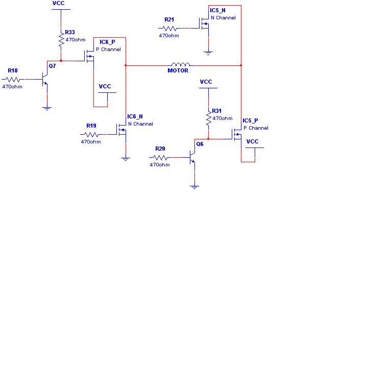
here’s an example of what I mean about the bjt’s. Credit’s goto Jshwaa at the xmodsrc forum for the schematic.
cheers,
ph2t.
here’s an example of what I mean about the bjt’s. Credit’s goto Jshwaa at the xmodsrc forum for the schematic.
cheers,
ph2t.
c’mon dave, spill ya bastard! what did it clock on the old tammy speed checker? what pinion was being used? and lastly, how many cells?
c’mon dave, spill ya bastard! what did it clock on the old tammy speed checker? what pinion was being used? and lastly, how many cells?
you can use a standard pnp BJT like the BC558 in a “pull up” arangment but I had the mosfet drivers on hand.
Also the mosfet drivers are specifically desinged to source high currents for those first few microseconds when the gate pin is not in it’s “enhancement ” state.
ph2t.
you can use a standard pnp BJT like the BC558 in a “pull up” arangment but I had the mosfet drivers on hand.
Also the mosfet drivers are specifically desinged to source high currents for those first few microseconds when the gate pin is not in it’s “enhancement ” state.
ph2t.
The issue was the p-chan mosfets. Now that I have the regulator setup to maintain a Vcc of 4.8V to the RX circuit the output from the RX circuit into the mosfets will be 4.8V for the “on” state and still 0V for the “off” state.
For a pchan to turn on the voltage at the gate pin must be at a lower potential than Vcc. For the pchan to be off the gate pin voltage must be at the same potential as Vcc.
Can you see the issue? Vcc for the nelly h-bridge is now 7.2V. But the gate pin potential will only be as high as 4.8V (the output signal from the kyosho RX PCB). For a 4.8V potential on the gate pin the mosfet would normally be off. BUT now there is two Vcc’s. The RX Vcc of 4.8V and the nelly Vcc of 7.2V. The pchan mosfet should be off, but now it isnt. The gate pin is 2.4V LESS than Vcc, this means that BOTH P-CHAN mosfets in the nelly h-bridge are on!!! All i did was push fwd on the TX and that turn on one of the n-chan mosfets. This caused a short circuit and therefore blew the p-chan (and eventually the nchan) mosfets.
To solve the problem i need to bring the output from the RX for an “off” signal (talking pchan here) of 4.8V to 7.2V. This way the pchans stay off and will only turn on when they are meant to.
I’ve decided to use a pair of Maxim mosfet driver IC’s. Don’t have the part number on hand, I will post it and a full schematic over the next few days. The mosfet driver is like a buffer and it will be connected to the Vcc of 7.2V. This will translate a 4.8V signal to a 7.2V one but keep a 0V signal at 0V. This should get around this issue. It will also alow me to turn the mosfets on even better and improve the Rds(on) value of the mosfets to an even lower figure and increase efficiency buy about %60.
Make sense? prolly not, lol…..
ph2t.
Quote:Did ya kiss the wookie, betty?:clown:I doubt he can bend over that far, ha!
OK fellas, the order has been placed.
Here’s the totals, see the last line for the amount you owe me.

PM me for payment details.
When the tracking number is given, I’ll post it here so you can all know the delivey status. Once I get it, I’ll send the sydney order to Dgs via express post.
Cheers,
ph2t.
OK fellas, the order has been placed.
Here’s the totals, see the last line for the amount you owe me.
PM me for payment details.
When the tracking number is given, I’ll post it here so you can all know the delivey status. Once I get it, I’ll send the sydney order to Dgs via express post.
Cheers,
ph2t.
I fried it! ARGGHHHHHHHHH! And I know why now as well. I’m an idiot, I should of picked up on it earlier.
Gotta change the design…..What a waste too! Those fets cost me $20SUD. shit shit shit shit shit!
:dead:
ph2t.
I fried it! ARGGHHHHHHHHH! And I know why now as well. I’m an idiot, I should of picked up on it earlier.
Gotta change the design…..What a waste too! Those fets cost me $20SUD. shit shit shit shit shit!
:dead:
ph2t.
not for sale….. purely an experimental version.
not for sale….. purely an experimental version.
hey kitsune, here’s how I solder the IRF6609 mosfets in nelly 1.2:

Tricky buggers, the DirectFET package the IRF6609’s use sinks heat so well that it’s very easy to re-melt previous solder joins whilst soldering the wire on, damn!!!!
Nelly Deluxe
She’s mah new baby. Not much really. It’s a nelly 1.2 with a 4.8V regulator setup. This allows me to run up to 20V (mosfet limit) into a chassis BUT still have a regulated 4.8V output to goto the rest of the receiver PCB. This way the RX and steering circuits are NOT affected by the increase in supply voltage, they will always be set at the safe level of 4.8V. The drive train part of nelly deluxe is wired straight into the high voltage source allowing it to take full advantage of this extra voltage.


more to come……
ph2t.
hey kitsune, here’s how I solder the IRF6609 mosfets in nelly 1.2:
Tricky buggers, the DirectFET package the IRF6609’s use sinks heat so well that it’s very easy to re-melt previous solder joins whilst soldering the wire on, damn!!!!
Nelly Deluxe
She’s mah new baby. Not much really. It’s a nelly 1.2 with a 4.8V regulator setup. This allows me to run up to 20V (mosfet limit) into a chassis BUT still have a regulated 4.8V output to goto the rest of the receiver PCB. This way the RX and steering circuits are NOT affected by the increase in supply voltage, they will always be set at the safe level of 4.8V. The drive train part of nelly deluxe is wired straight into the high voltage source allowing it to take full advantage of this extra voltage.
more to come……
ph2t.
why? what has he got running?
why? what has he got running?
my cat’s breath smells like cats food……
-
AuthorPosts